Embedded magnetic path structure of high-performance permanent-magnet synchronous servo motor rotor

A permanent magnet synchronous, servo motor technology, applied in the field of servo motors, can solve the problems of high magnetic steel temperature, narrow speed regulation range, low power density and so on

Pending Publication Date: 2019-02-15
苏州德迈科电机技术有限公司
View PDF0 Cites 0 Cited by
  • Summary
  • Abstract
  • Description
  • Claims
  • Application Information

AI Technical Summary

Problems solved by technology

[0002] Most of the magnetic circuit of the general servo permanent magnet synchronous motor adopts a distributed winding structure, and adopts a magnetic circuit design with multi-slot pole matching. Copper coils are wound on the stator laminations to cooperate with the rotor laminations. The inner surface of the rare earth permanent magnet steel is attached to the rotor. On the laminations, the structure of stainless steel sle

Method used


Image

  • Embedded magnetic path structure of high-performance permanent-magnet synchronous servo motor rotor
  • Embedded magnetic path structure of high-performance permanent-magnet synchronous servo motor rotor
  • Embedded magnetic path structure of high-performance permanent-magnet synchronous servo motor rotor

Examples


Embodiment

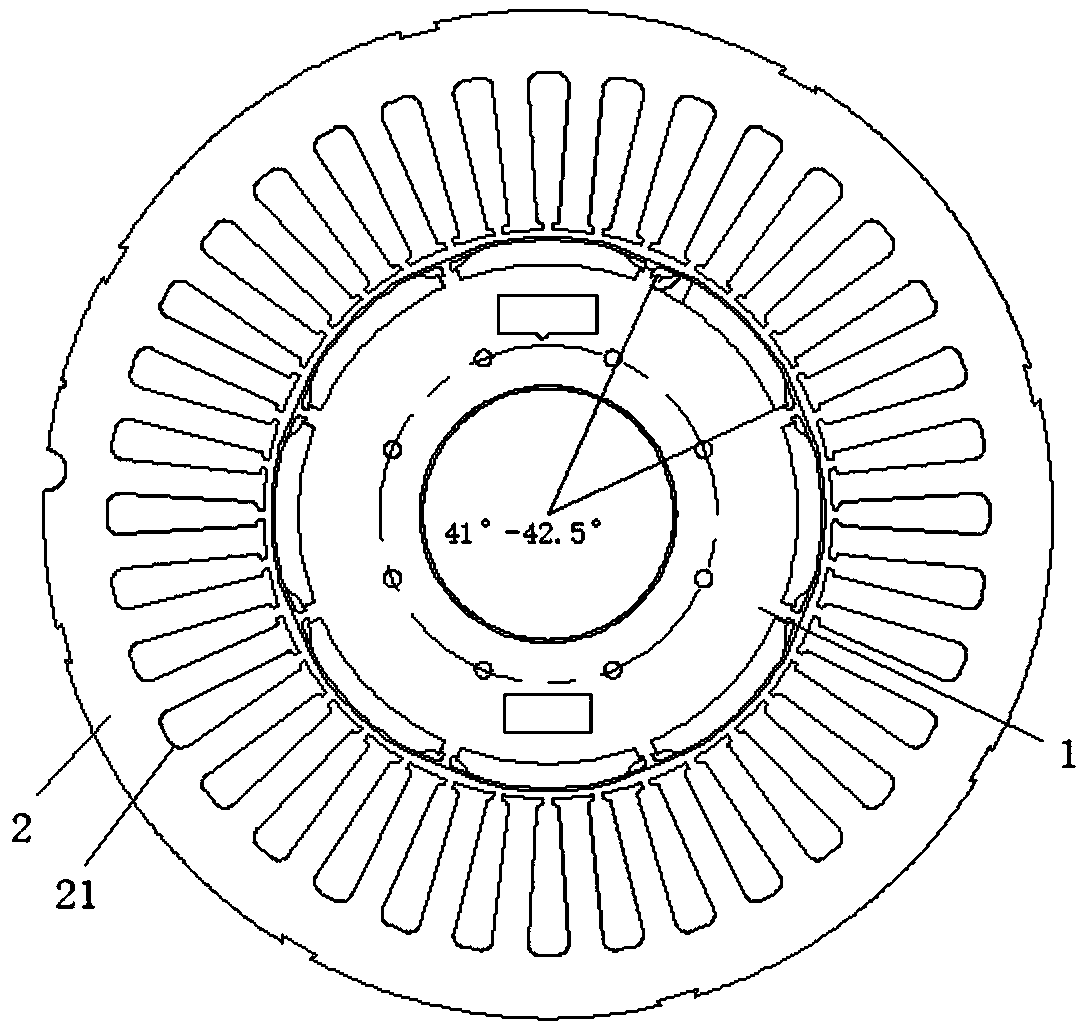
[0021] refer to Figure 1-4 As shown, this embodiment is a high-performance permanent magnet synchronous servo motor rotor embedded magnetic circuit structure, including a rotor punch 1, a stator punch 2 arranged on the outer periphery of the rotor punch 1, and a magnet set in the rotor punch 2. steel components;

[0022] There is an annular vacancy 11 between the rotor punch 1 and the stator punch 2; the inner circumference of the stator punch 2 is provided with a number of slots 21 for accommodating coils arranged at equidistant intervals, and the ends of each slot 21 are in contact with the vacancy 11. connected.

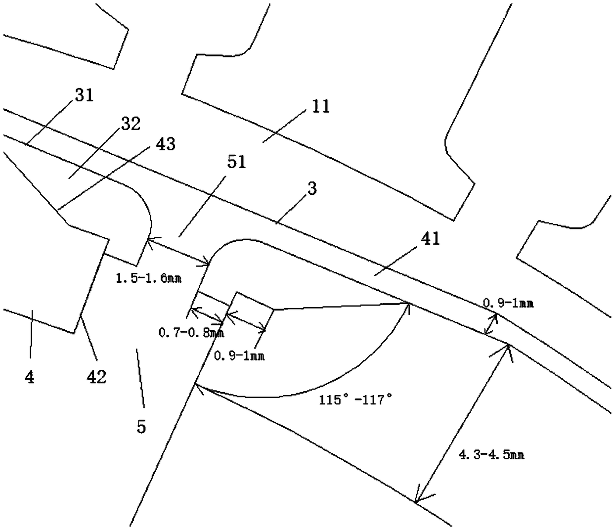
[0023] The rotor punch 1 includes an annular rotor core 3 and a plurality of holes 31 arranged at equal intervals on the outer periphery of the rotor core 3 .

[0024] The magnetic steel assembly includes the magnetic steel 4 arranged in the hole 31, the magnetic spacer bridge arranged between the adjacent holes, and the rotor core bulge 41 arranged between the...


PUM

PropertyMeasurementUnit
Zhang jiaoaaaaaaaaaa
Angleaaaaaaaaaa
Widthaaaaaaaaaa

Abstract

The invention discloses an embedded magnetic path structure of a high-performance permanent-magnet synchronous servo motor rotor. The embedded magnetic path structure comprises a rotor punching sheet,a stator punching sheet and a magnetic steel assembly, wherein the stator punching sheet is arranged at the periphery of the rotor punching sheet, the magnetic steel assembly is arranged in the rotorpunching sheet, annular vacancy is reserved between the rotor punching sheet and the stator punching sheet, the rotor punching sheet comprises an annular rotor iron core and a plurality of hole sites, the plurality of hole sites are arranged at the periphery of the rotor iron core at equal distance, the magnetic steel assembly comprises magnetic steel, a magnetic isolation bridge and a rotor ironcore protruding part, the magnetic steel is arranged in the hole sites, the magnetic isolation bridge is arranged between adjacent hole sites, the rotor iron core protruding part is arranged betweenthe magnetic steel and the vacancy, right-angle parts are respectively arranged at two ends of an inner site of the magnetic steel, inclination parts are respectively arranged at two ends of an outerside of the magnetic steel, connection positions of the inclination parts and the right-angle parts are space parts of the hole sites, the magnetic isolation bridge comprises a first step part and a second step part, the first step part is arranged between the right-angle parts of adjacent magnetic steel, and the second step part is arranged between the space parts at adjacent sites. By the embedded magnetic path structure, the permanent-magnet synchronous servo motor magnetic path has the advantages of high reliability, high power density, wide speed regulation range, high efficiency and thelike.

Description

technical field [0001] The invention belongs to the technical field of servo motors, in particular to a high-performance permanent magnet synchronous servo motor rotor embedded magnetic circuit structure. Background technique [0002] Most of the magnetic circuit of the general servo permanent magnet synchronous motor adopts a distributed winding structure, and adopts a magnetic circuit design with multi-slot pole matching. Copper coils are wound on the stator laminations to cooperate with the rotor laminations. The inner surface of the rare earth permanent magnet steel is attached to the rotor. On the laminations, a stainless steel sleeve structure is added outside. The disadvantages of this structure are: low efficiency, low power density, narrow speed range, and high temperature of the magnetic steel. The use and application requirements of permanent magnet synchronous servo motors are becoming more and more stringent. Under the same power factor, the volume and weight of...

Claims


Application Information

Patent Timeline
IPC IPC(8): H02K21/02H02K1/16H02K1/27
CPCH02K21/02H02K1/16H02K1/2766H02K21/028H02K2213/03
Inventor 何建军谭新德易志辉
Owner 苏州德迈科电机技术有限公司
Why Eureka
Try Eureka