Supercharge Your Innovation With Domain-Expert AI Agents!

Gradient Diffuser

A technology of diffusers and main surfaces, applied in the field of gradient diffusers, which can solve problems such as unpleasant lighting intensity changes

Active Publication Date: 2019-12-10
3M INNOVATIVE PROPERTIES CO
View PDF10 Cites 0 Cited by
  • Summary
  • Abstract
  • Description
  • Claims
  • Application Information

AI Technical Summary

Problems solved by technology

Unpleasant lighting intensity variations near the input edges of the backlight may sometimes be seen in the display

Method used


Image

  • Gradient Diffuser
  • Gradient Diffuser
  • Gradient Diffuser

Examples


preparation example Construction

[0097] Instead of using the original tool itself in the preparation of the optical diffuser film, one or more replica tools can be prepared by microreplicating the structured second major surface of the original tool, which can then be used to prepare the diffuser. The structured surface of the projectile. The first replica made from the original tool will have the first replica structured surface corresponding to the inverse version of the structured second major surface. For example, protrusions on the structured second major surface correspond to cavities on the first replica structured surface. A second replica can be made from the first replica. The second replica will have a second replica structured surface that corresponds to and is a non-inverted version of the structured second major surface of the original tool.

[0098] After step 904, after forming the structured surface tool, a surface having the same structure (whether inverted or non-inverted relative to the ...

Embodiment

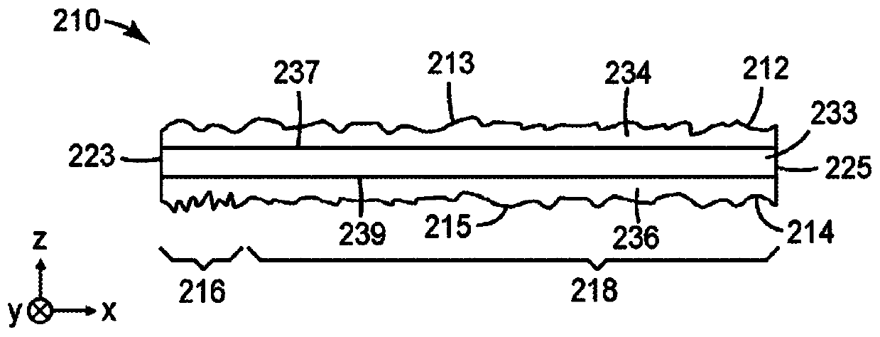
[0136] edge gradient diffuser

[0137]The graded diffuser film was prepared as follows. An electroplated cylindrical microreplication tool was cut using an engraver with a 110° apex angle diamond to create a set of hexagonal indentations of varying depth around the perimeter of the tool. When the diamond cuts deeper into the tool, more surface area of ​​the tool is affected; when the diamond cuts shallower, less surface area of ​​the tool is affected. The first 10 mm of the hexagonal indentation on the tool is the deepest. The depth decreases monotonically for the next 13 mm to about 23 mm around the perimeter. For from 10 mm to about 17 mm, the depth decreases in a curve corresponding approximately to a cubic spline. For from about 17 mm to about 23 mm, the depth varies linearly until a constant depth continues around the perimeter of the tool. In this way a plurality of parallel circumferential cuts are formed.

[0138] The on-tool structures were then microreplicated...

Embodiment approach 1

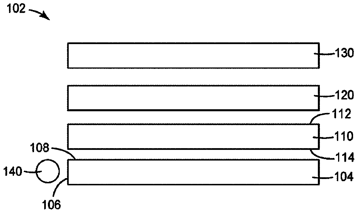
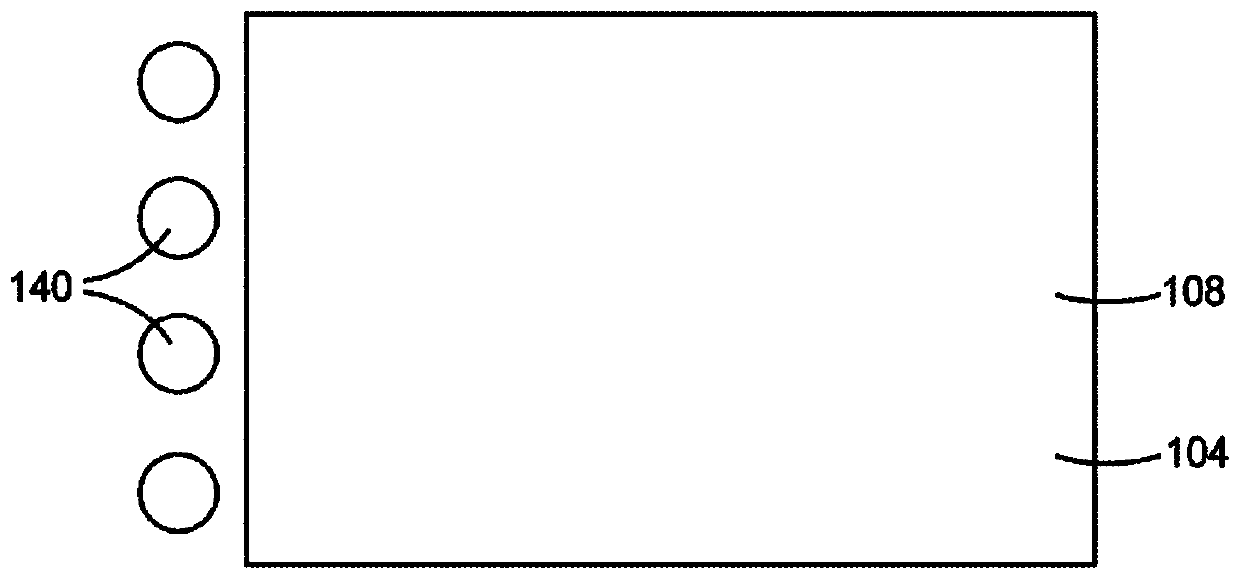
[0148] Embodiment 1 is a diffuser comprising: opposing first and second major surfaces and an edge extending between the first and second major surfaces, wherein the first major surface The surface includes a plurality of first surface structures providing a substantially uniform first haze, the second major surface includes a first portion adjacent to the edge and a second portion adjacent to the first portion and opposite the edge, the first portion includes a an edge-adjacent first region and a second region located between the first region and the second portion, wherein the second major surface comprises a plurality of second portions providing a substantially uniform second haze on the second major surface and A second surface structure providing a third haze at the first portion of the second major surface, wherein the third haze is substantially equal to the second haze along a continuous boundary between the first portion and the second portion of the second major surf...


PUM

PropertyMeasurementUnit
angleaaaaaaaaaa
angleaaaaaaaaaa
angleaaaaaaaaaa

Abstract

The present invention describes a diffuser comprising opposing structured first and structured second major surfaces. The first major surface includes a plurality of first surface structures that provide a uniform first haze. The second major surface includes a first portion adjacent to the edge and a second portion adjacent to the first portion. The first portion includes a first area and a second area between the first area and the second portion. The second major surface includes a plurality of second surface structures that provide a uniform second haze over the second portion and provide a third haze in the first portion. The third haze in the first region is greater than the second haze, and the third haze in the second region decreases monotonically. The surface area of ​​the second portion is at least 90% of the surface area of ​​the second major surface.

Description

Background technique [0001] A backlight used in a liquid crystal display (LCD) may include a light guide and a plurality of light emitting diodes (LEDs) that inject light into the input edge of the light guide. A diffuser may be included in the display between the light guide and the LCD panel. Unpleasant lighting intensity variations near the input edges of the backlight may sometimes be seen in the display. Contents of the invention [0002] In some aspects of the present specification, a diffuser is provided that includes opposing first and second major surfaces and an edge extending between the first and second major surfaces. The first major surface includes a plurality of first surface structures providing a substantially uniform first haze, and the second major surface includes a first portion adjacent to the edge and a second portion adjacent to the first portion and opposite the edge. The first portion includes a first region adjacent to the edge and a second regi...

Claims


Application Information

Patent Timeline
Patent Type & Authority Patents(China)
IPC IPC(8): G02B6/00G02B1/115G02B5/02
CPCC25D5/12C25D7/00C25D5/605G02B3/005G02B3/0062G02B5/0221G02B5/0242G02B5/0263G02B5/0268G02B5/0278G02B6/0051G02B6/0061G02B1/14G02F1/133607G02B1/115G02B5/02C25D3/04C25D3/38G02B5/0284G02B5/04G02B6/0053G02B6/0076G02F1/133603G02F1/133606
Inventor 加里·T·博伊德特里·D·彭尼古拉斯·A·约翰逊莺·V·彭萨拉·S·梅里特斯蒂芬·J·埃茨科恩张海燕科里·D·巴茨约瑟夫·T·阿伦森
Owner 3M INNOVATIVE PROPERTIES CO
Features
  • R&D
  • Intellectual Property
  • Life Sciences
  • Materials
  • Tech Scout
  • Unparalleled Data Quality
  • Higher Quality Content
  • 60% Fewer Hallucinations
Learn More