Supercharge Your Innovation With Domain-Expert AI Agents!

A drip irrigation device

A dripper and body technology, applied in the field of drip irrigation pipe structure, can solve problems such as inability to solve crops and insignificant benefits, and achieve the effect of saving costs and speeding up production efficiency

Active Publication Date: 2020-04-21
恩施州悠鼎茶业有限公司
View PDF2 Cites 1 Cited by
  • Summary
  • Abstract
  • Description
  • Claims
  • Application Information

AI Technical Summary

Problems solved by technology

The use of this patent is directional. Specifically, the water inlet direction in the direction of the pipe body must be fixed. At the same time, because the watering area is connected to the main pipe area, the pressure in the watering area is almost the same. The problem of crop roots invading drippers

Method used


Image

  • A drip irrigation device

Examples


Embodiment Construction

[0021] The specific implementation of the invention will be further described below in conjunction with the accompanying drawings.

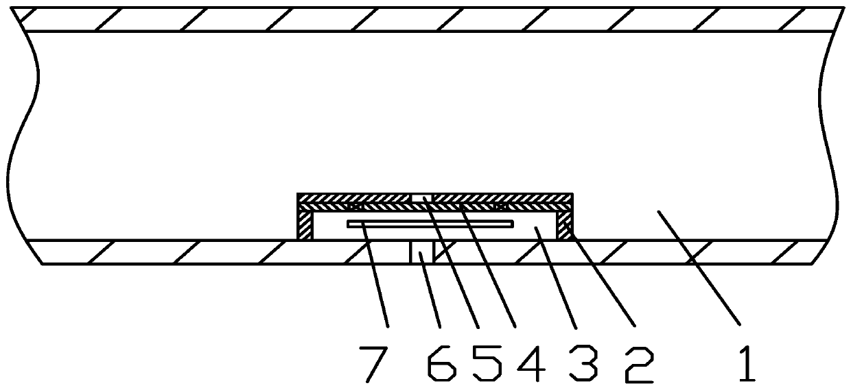
[0022] Such as figure 1 As shown, the drip irrigation device includes a pipe body 1 , a dripper and a copper sheet 7 .

[0023] The dripper is arranged in the tube body 1, and is evenly arranged along the axial direction of the tube body 1; the dripper includes a dripper body 2 and an elastic diaphragm 4, and the dripper body 2 has a cavity 3, and the dripper body 2 faces the tube One end of the body 1 is provided with a water inlet hole 5 , and the opposite end is provided with a water outlet hole 6 exposed to the tube body 1 , both the water inlet hole 5 and the water outlet hole 6 are connected to the cavity 3 . The elastic diaphragm 4 is located in the inner cavity 3 of the dripper body 2 and is connected to the dripper body 2 through multiple rows of bonding points. The elastic diaphragm 4 corresponds to the water inlet 5, and the multiple ...


PUM


Abstract

The invention discloses a trickle irrigation device, and belongs to a trickle irrigation pipe structure. The trickle irrigation device includes a pipe body and emitters, wherein the emitters are arranged in the pipe body and evenly distributed in the axial direction of the pipe body; each emitter is composed of an emitter body and an elastic membrane, each emitter body is internally provided witha containing cavity, the end, facing the pipe body, of each emitter body is provided with a water inlet, the opposite end of each emitter body is provided with a water outlet positioned outside the pipe body, and each water inlet and the corresponding water outlet are both communicated with the corresponding containing cavity; each elastic membrane is positioned in the containing cavity in the corresponding emitter body and connected with the corresponding emitter body through multiple rows of bonding points; each elastic membrane corresponds to one water inlet, the rows of bonding points areintersected with one another to form water-permeable passages communicated with the water inlets, and the water-permeable passages are provided with copper sheets arranged inside the containing cavities in a honeycomb shape. The trickle irrigation device has the advantages of being capable of being simple in structure, low in cost, great in popularization value and capable of solving the technicalproblem that a plant root system blocks the passageways of the emitters.

Description

technical field [0001] The invention relates to a drip irrigation pipe structure, in particular to a drip irrigation device. Background technique [0002] Drip irrigation is by far one of the most water-saving irrigation techniques for farmland irrigation. However, because of its high price, it was once called "expensive technology", and it was only used in high value-added economic crops. The flood irrigation method currently used in most areas not only needs to waste a lot of water resources, but also due to the amount of water If it is too large, the air permeability of the soil will be reduced during the irrigation stage, and it will easily cause soil compaction. The root system of crops may penetrate the capillary or invade the dripper, rodents and insects gnaw, and the system maintenance is difficult and other problems still exist, which leads to the development of buried drip irrigation technology is far behind. [0003] Patent 201310237141.0 discloses a dropper, wh...

Claims


Application Information

Patent Timeline
Patent Type & Authority Patents(China)
IPC IPC(8): A01G25/06
CPCY02A40/22
Inventor 谢英健
Owner 恩施州悠鼎茶业有限公司
Features
  • R&D
  • Intellectual Property
  • Life Sciences
  • Materials
  • Tech Scout
  • Unparalleled Data Quality
  • Higher Quality Content
  • 60% Fewer Hallucinations
Learn More