
X-ray film viewing device for imaging department

A light film and film viewing technology, applied in the field of imaging, can solve the problems of poor film viewing effect and affecting the accuracy of film viewing

Inactive Publication Date: 2018-01-05
史志成
View PDF6 Cites 9 Cited by
  • Summary
  • Abstract
  • Description
  • Claims
  • Application Information

AI Technical Summary

Problems solved by technology

[0006] In order to overcome the shortcomings of the current X-ray film viewing equipment, such as inflexibility and poor film viewing effect, which affect the accuracy of film viewing, the technical problem to be solved by the present invention is to provide a device that can flexibly move, adjust, and film viewing effects High-quality, high-accuracy X-ray film viewing equipment for imaging science

Method used


Image

  • X-ray film viewing device for imaging department
  • X-ray film viewing device for imaging department
  • X-ray film viewing device for imaging department

Examples


Embodiment 1

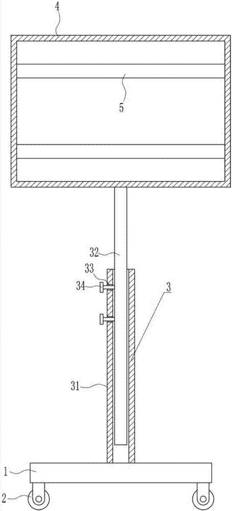
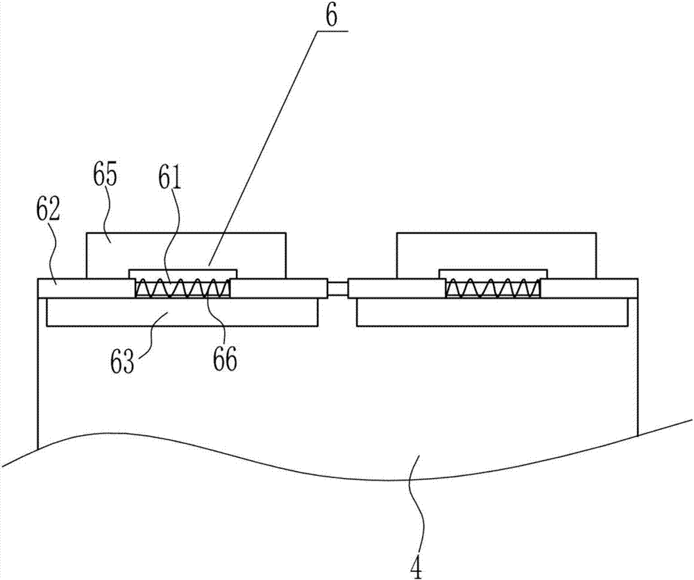
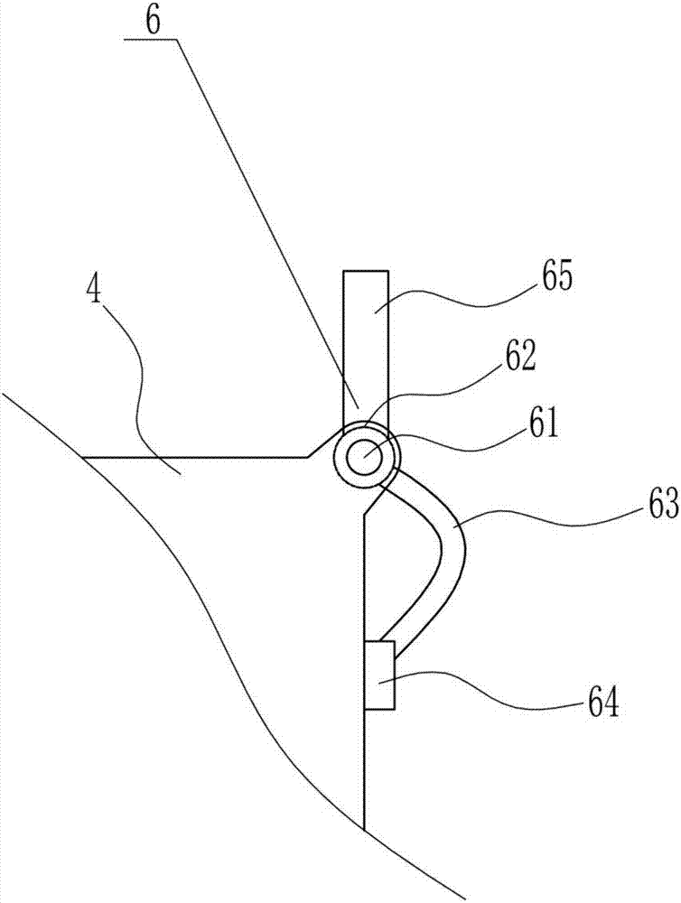
[0042] A kind of X-ray film viewing equipment for imaging department, such as Figure 1-11 As shown, it includes base plate 1, wheel 2, lifting device 3, light box 4, lamp tube 5 and clamping device 6, and the four corners of the bottom of base plate 1 are all equipped with wheels 2 by means of bolt connection, and the middle of base plate 1 top is provided with Lifting device 3 is arranged, and the lifting part top of lifting device 3 is provided with light box 4, and lamp tube 5 is installed in the light box 4 by the mode of bolt connection, and the left and right sides of light box 4 front side tops are all provided with clamping device 6.

Embodiment 2

[0044] A kind of X-ray film viewing equipment for imaging department, such as Figure 1-11 As shown, it includes base plate 1, wheel 2, lifting device 3, light box 4, lamp tube 5 and clamping device 6, and the four corners of the bottom of base plate 1 are all equipped with wheels 2 by means of bolt connection, and the middle of base plate 1 top is provided with Lifting device 3 is arranged, and the lifting part top of lifting device 3 is provided with light box 4, and lamp tube 5 is installed in the light box 4 by the mode of bolt connection, and the left and right sides of light box 4 front side tops are all provided with clamping device 6.

[0045] The lifting device 3 includes a sleeve 31, a sliding rod 32 and a screw rod 34. The middle of the top of the bottom plate 1 is connected with a sleeve 31 by means of a bolt connection. The sleeve 31 is vertically arranged, and the sliding type in the sleeve 31 is provided with a sliding rod 32. The sliding rod 32 cooperates with ...

Embodiment 3

[0047] A kind of X-ray film viewing equipment for imaging department, such as Figure 1-11 As shown, it includes base plate 1, wheel 2, lifting device 3, light box 4, lamp tube 5 and clamping device 6, and the four corners of the bottom of base plate 1 are all equipped with wheels 2 by means of bolt connection, and the middle of base plate 1 top is provided with Lifting device 3 is arranged, and the lifting part top of lifting device 3 is provided with light box 4, and lamp tube 5 is installed in the light box 4 by the mode of bolt connection, and the left and right sides of light box 4 front side tops are all provided with clamping device 6.

[0048] The lifting device 3 includes a sleeve 31, a sliding rod 32 and a screw rod 34. The middle of the top of the bottom plate 1 is connected with a sleeve 31 by means of a bolt connection. The sleeve 31 is vertically arranged, and the sliding type in the sleeve 31 is provided with a sliding rod 32. The sliding rod 32 cooperates with ...


PUM


Abstract

The invention relates to the field of the imaging department, in particular to an X-ray film viewing device for the imaging department. The X-ray film viewing device is characterized in that the X-rayfilm viewing device can be moved and adjusted flexibly an is good in film viewing effect and high in accuracy. The X-ray film viewing device comprises a baseplate and the like; wheels are mounted atthe four corners of the bottom of the baseplate in a bolt connection mode, a lifting device is arranged in the middle of the top of the baseplate, and a lamp box is arranged on the top of a lifting component of the lifting device; lamp tubes are mounted in the lamp box in a bolt connection mode, and clamping devices are arranged on both the left side and the right side of the upper portion of thefront side of the lamp box. The X-ray film viewing device can be moved through the wheels, the lifting device and a rotation device adjust the height and angle of the lamp box, accordingly an X-ray film can be viewed more conveniently, and the effects of flexible moving and adjustment, good film viewing effect and high accuracy are achieved.

Description

technical field [0001] The invention relates to the field of imaging department, in particular to an X-ray film viewing device for imaging department. Background technique [0002] Medical imaging refers to the technology and processing process of obtaining internal tissue images of the human body or a certain part of the human body in a non-invasive manner for medical treatment or medical research. It includes the following two relatively independent research directions: medical imaging system and medical image processing. The former refers to the process of image formation, including the research on imaging mechanism, imaging equipment, imaging system analysis and other issues; the latter refers to the further processing of the obtained image, the purpose of which is to make the original image that is not clear enough Restoration, or to highlight certain feature information in the image, or to classify the image as a pattern. [0003] X-ray film is X-ray penetrating radi...

Claims


Application Information

Patent Timeline
IPC IPC(8): G02B27/02
Inventor 史志成秦静文张维洁
Owner 史志成
Learn More