Route planning method applied to rotor UAV

A rotorless unmanned and unmanned aerial vehicle technology, applied in the field of remote sensing mapping and aerial photography, can solve the problem of not considering route planning, not considering the movement path and reachable area of ​​a single operator, not considering the reachable operation route of the operator and Work efficiency optimization and other issues to achieve the effect of reducing workload

Active Publication Date: 2018-01-05
土豆数据科技集团有限公司
View PDF8 Cites 24 Cited by
  • Summary
  • Abstract
  • Description
  • Claims
  • Application Information

AI Technical Summary

Problems solved by technology

Most of the existing route planning methods are based on planning for a single flight in a designated area, and basically do not plan for the poor endurance of the rotor UAV, the need for frequent take-offs and landings, battery replacement, etc., and basically do not consider multiple unmanned aerial

Method used


Image

  • Route planning method applied to rotor UAV
  • Route planning method applied to rotor UAV
  • Route planning method applied to rotor UAV

Examples


Embodiment 1

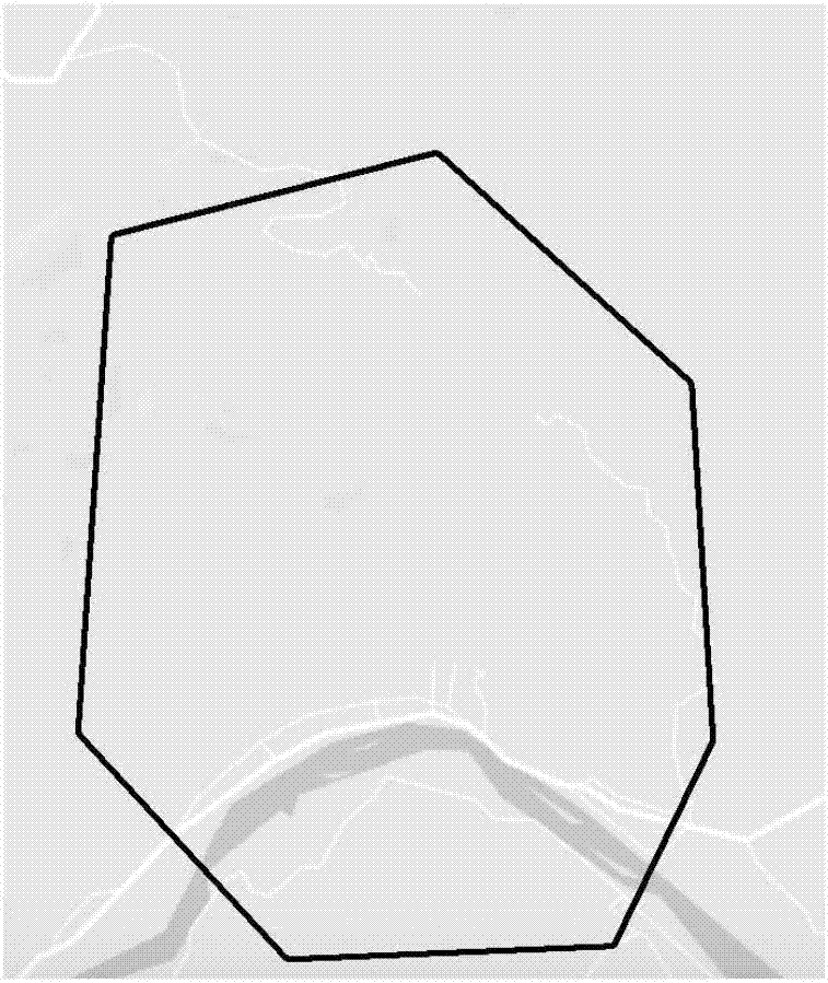
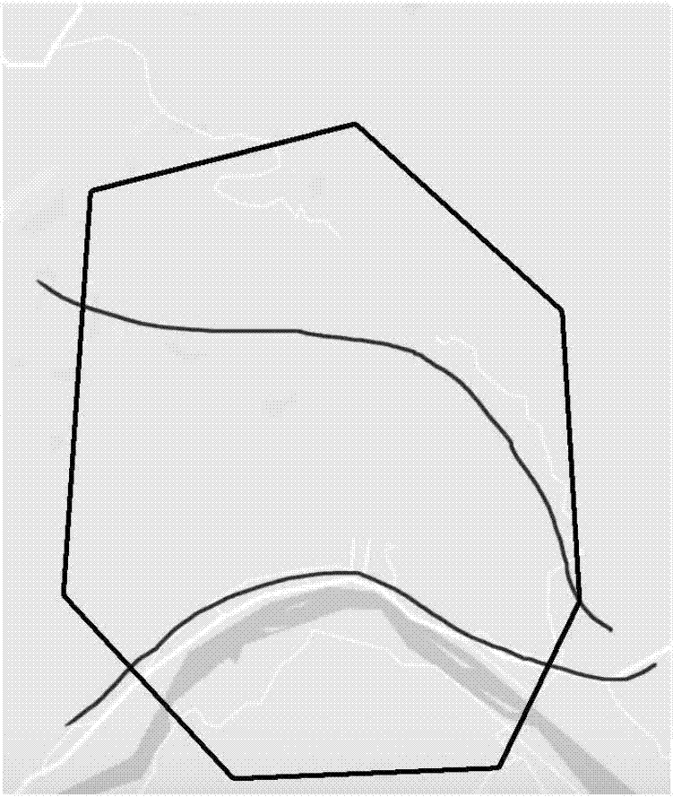
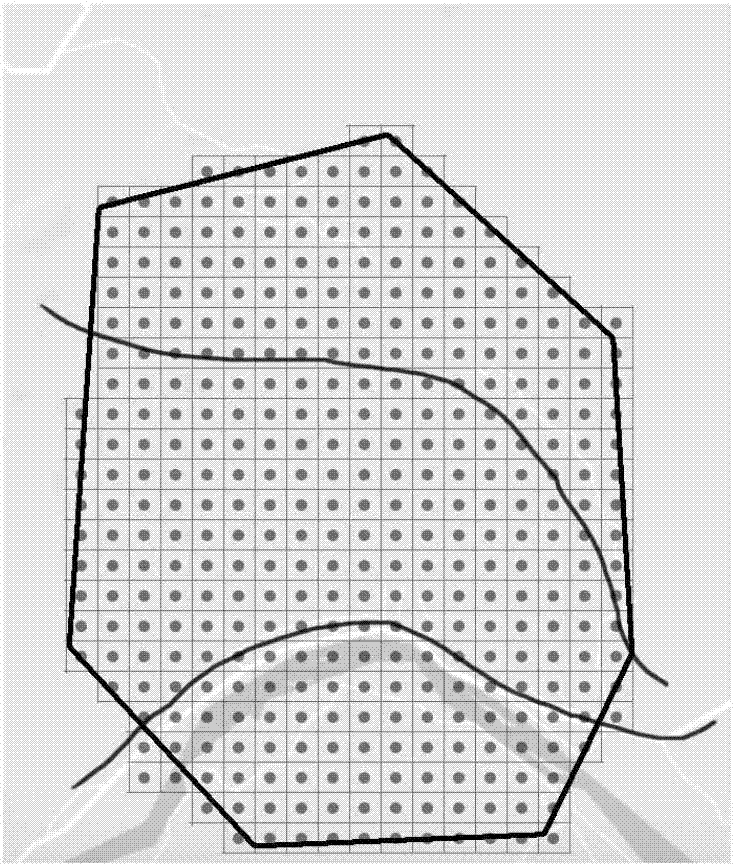
[0040] Reference attached Figure 1-4 As shown, a large area segmented route planning method of the present invention applied to rotary wing drones specifically divides a user-specified area into several grids according to the coverage of a single image and the required overlap rate. Each grid contains an image collection point; the maximum number of image collection points for a single voyage is calculated according to the drone's single endurance; the operating route of the drone operator is automatically generated according to the user's delineation or algorithm. The route selects the take-off point and the landing point; the entire area is automatically divided into multiple flight routes according to the maximum number of image acquisition points in a single time and the total number of grids contained in the entire area; multiple routes are automatically grouped according to the number of flight groups entered by the user.

[0041] In this embodiment, it specifically includ...

Embodiment 2

[0070] As a further improvement of Example 1, refer to Figure 5 As shown, the algorithm divides the flight routes into W flight route groups according to the number of UAV operators W. Generally, all flight operations of each flight route group are performed by the same drone operator. In order to reduce the transition and movement of drone operators, the flight routes are grouped according to the operating route, and the algorithm ensures that the take-off and landing points of the same group of flight routes are located on the same operating route.

[0071] In this embodiment, according to the number of route groups W and the operation routes input by the user, the operation routes of different route groups may be the same or different. Reference attached Figure 5 It can be seen that, in this embodiment, there are two groups of route groups, group A and group B.


PUM


Abstract

The invention discloses a route planning method applied to a rotor UAV. The method comprises the steps of drawing an operation route, a step of meshing, a step of calculating a maximum number of imagepickup acquisition points, a step of planning an air route, and a step of selecting a takeoff point and a landing point, wherein a grid which intersects or is adjacent to the operation route is a first image pickup acquisition point in the air route, a second image pickup acquisition point, a third image pickup acquisition point to an Nth image pickup acquisition point are orderly selected, N isa natural number, the takeoff point is selected from a position nearest to the first image pickup acquisition point, and the landing point is selected from a position nearest to the Nth image pickup acquisition point in the air route in the operation route where the takeoff point is located. According to the method, through automatically selecting the takeoff point and the landing point, the workload brought by the manual selection of the takeoff point and the landing point is reduced, and the generation of takeoff and landing points that a UAV operator can not reach is avoided.

Description

Technical field [0001] The invention belongs to the technical field of remote sensing mapping and aerial photography, and relates to a method for route planning applied to coordinated aerial photography of multiple rotor drones in large-area aerial photography operations. Background technique [0002] When using drones for photogrammetry, low-altitude photography is carried out through the camera mounted on the drone to obtain ground information. In order to ensure the image accuracy and coverage overlap of UAV aerial photography, it is necessary to plan the flight route of UAV. [0003] Due to the weak endurance of rotary-wing UAVs, for large-area flight photogrammetry, multiple flights or coordination of multiple UAVs are required for flight measurement. The take-off and landing of rotary-wing drones and battery replacement will increase the operating time. Therefore, it is necessary to ensure that the battery life is fully utilized in each flight operation in the route planning...

Claims


Application Information

Patent Timeline
IPC IPC(8): G05D1/10
Inventor 董建平吉伟勇董秋逸
Owner 土豆数据科技集团有限公司
Why Eureka
Try Eureka