
Iron core lamination platform of rolled iron core transformer

A technology of transformer iron core and lamination table, which is applied in the field of transformer manufacturing, can solve the problems of increasing the difficulty of winding winding and reducing the ability of short circuit, etc., and achieves the effect of simple structure, changing working state, and high lamination precision

Inactive Publication Date: 2018-01-05
黄石市金雀电气股份有限公司
View PDF0 Cites 0 Cited by
  • Summary
  • Abstract
  • Description
  • Claims
  • Application Information

AI Technical Summary

Problems solved by technology

The winding must be wound on the iron core, which increases the difficulty of winding the winding, and because the low-voltage winding cannot be wound in foil, its ability to withstand short circuit is reduced

Method used


Image

  • Iron core lamination platform of rolled iron core transformer
  • Iron core lamination platform of rolled iron core transformer
  • Iron core lamination platform of rolled iron core transformer

Examples


Embodiment Construction

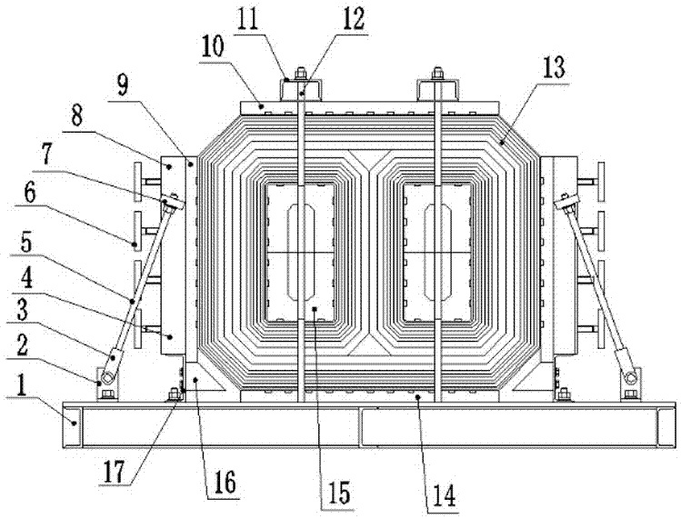
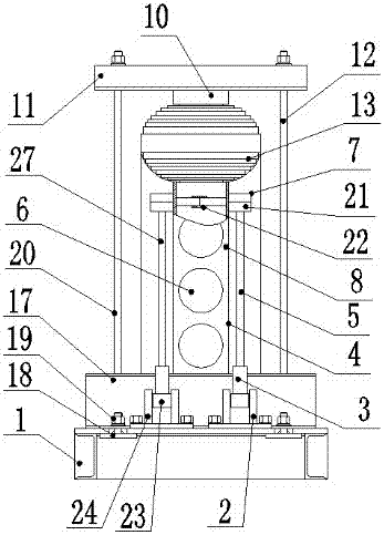
[0017] Such as figure 1 and figure 2 As shown, the winding core transformer core lamination platform includes a base 1, the upper surface of the base 1 is provided with a lower backing plate 14, and a plurality of front screw rods located on the front side of the lower backing plate are installed on the base 1 12 and the rear screw rod 20 located at the rear side of the lower backing plate, the corresponding front screw rod 12 and the rear screw rod 20 are equipped with a top pressure plate 11 at the end far away from the base 1, and a plurality of the top pressure plates 11 A backing board 10 is installed on the lower surface of the lower backing board 14 at a position corresponding to the lower backing board 14, and a topping device is respectively provided on the left side and the right side of the lower backing board 14 on the base 1.

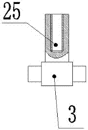
[0018] Such as figure 1 , figure 2 , image 3 , Figure 4 and Figure 5 As shown, the tightening device includes a first bracket 2...


PUM


Abstract

The invention relates to an iron core lamination platform of a rolled iron core transformer. The iron core lamination platform comprises a base and two core plates, wherein a lower backup plate is arranged on the upper surface of the base; a plurality of front screw rods located on the front side of the lower backup plate and a plurality of rear screw rods located on the rear side of the lower backup plate are mounted on the base; a plurality of top pressure plates are mounted at the ends, far away from the base, of the front screw rods and the rear screw rods in corresponding positions; top backup plates are mounted on the lower surfaces of the top pressure plates corresponding to the lower backup plate; jacking devices are respectively arranged on the base located on the left side and the right side of the lower backup plate; the two core plates are respectively mounted in two inner cavities of an iron core; and a plurality of grooves are uniformly formed in contact surfaces among baffle plates, the lower backup plate, the top backup plates and the iron core. According to the iron core lamination platform, the transformer iron core is shaped by the core plates and the jacking devices on the four sides; the clamping reliability of the iron core is high; the lamination precision is high; the dimension consistency is ensured; a reject ratio of a product is reduced; and the production cost is lowered.

Description

technical field [0001] The invention relates to the field of transformer manufacturing, in particular to a winding iron core transformer iron core lamination platform. Background technique [0002] In the existing distribution transformer wound core technology field, there is a three-phase triangular three-dimensional wound core transformer, and a three-phase planar wound core structure. But the coil cores are all closed. The winding must be wound on the iron core, which increases the difficulty of winding the winding, and because the low-voltage winding cannot be wound in foil, its ability to withstand short circuit is reduced. [0003] Combined with foreign equipment manufacturing technology, a new winding core transformer manufacturing technology has recently been introduced in China. Its advantage is that the winding core can be made into a form, and the transformer winding can be wound on the existing equipment, and then put on the winding iron core. On the iron core ...

Claims


Application Information

Patent Timeline
IPC IPC(8): H01F41/02B25B11/00
Inventor 金敏
Owner 黄石市金雀电气股份有限公司
Learn More