
Power distribution network fault detection device

A distribution network fault and detection device technology, applied in the field of distribution network, can solve the problems of small adjustability of maintenance clips, unstable clamping of circuit lines, waste of time for maintenance workers, etc., to improve work efficiency and convenience, Improvement of convenience and safety, effect of improving convenience

Pending Publication Date: 2021-10-08
谭文文
View PDF0 Cites 0 Cited by
  • Summary
  • Abstract
  • Description
  • Claims
  • Application Information

AI Technical Summary

Problems solved by technology

[0002] In the process of power transmission, in order to ensure the normal operation of the transmission, it is often necessary to carry out fault inspection on the power distribution network. When the electric power is repaired, it is necessary to use a fault detection device, and it is often necessary to clamp the circuit with a clip to detect the fault. The existing The adjustment of the maintenance clip is small, the applicability is poor, and the clamping of the circuit line is unstable, resulting in errors in the detection results, which not only wastes the time of the maintenance workers, but also affects work efficiency, and the instability when clamping will lead to serious problems. safety accidents, a distribution network fault detection device is proposed to solve the above-mentioned problems

Method used


Image

  • Power distribution network fault detection device
  • Power distribution network fault detection device
  • Power distribution network fault detection device

Examples


Embodiment Construction

[0021] use Figure 1-Figure 6 A distribution network fault detection device according to an embodiment of the present invention is described as follows.

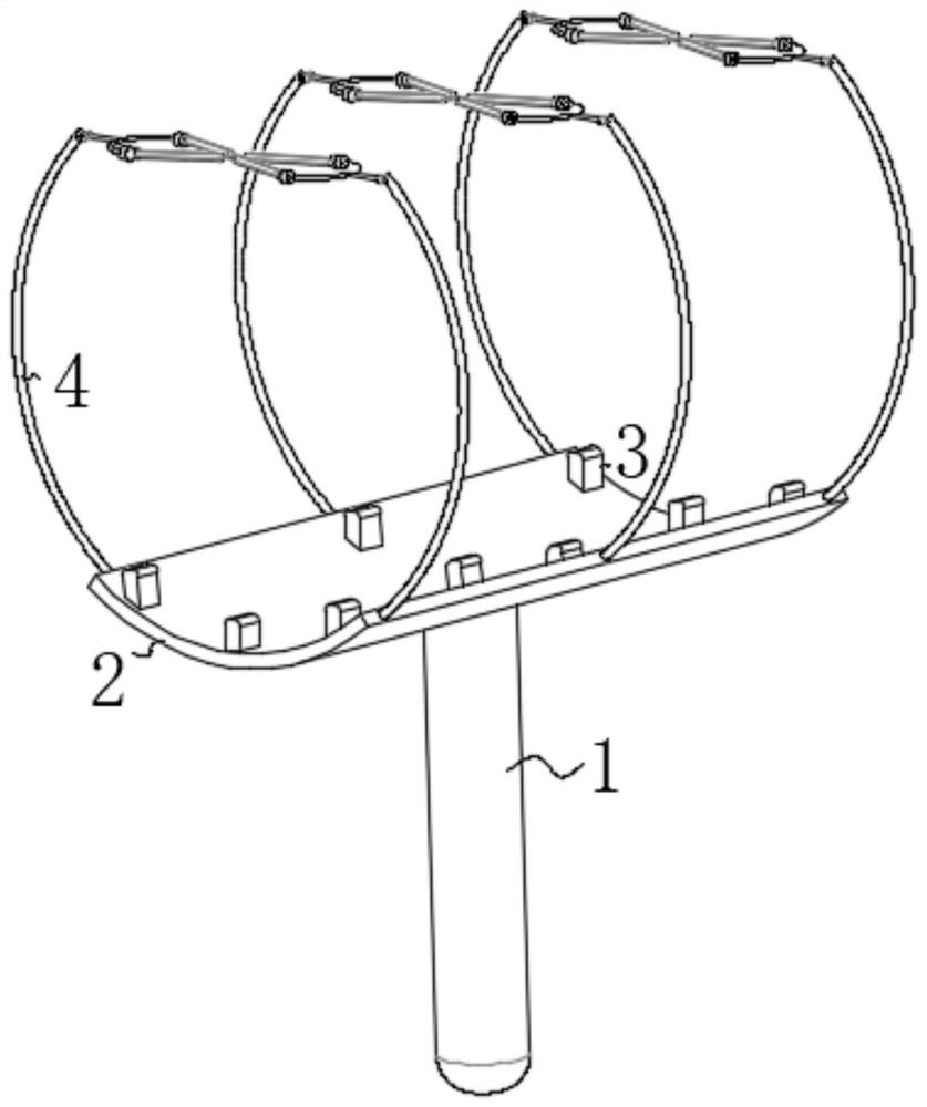
[0022] Such as Figure 1-Figure 6 As shown, a distribution network fault detection device of the present invention includes a handle 1; the top of the handle 1 is provided with a contact plate 2, and the top of the handle 1 is fixedly connected to the bottom of the contact plate 2, and the top of the contact plate 2 is uniformly arranged There is a contact block 3, and the top of the contact plate 2 is fixedly connected to the bottom of the contact block 3, the two ends of the contact plate 2 are uniformly provided with a fastening mechanism 4, and the bottom of the fastening mechanism 4 is fixedly connected to the inner wall of the contact plate 2, and the The purpose of the contact block 3 is to prevent insecure clamping.

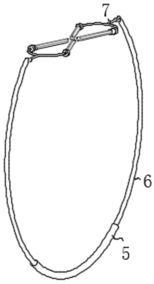
[0023] The fastening mechanism 4 includes a storage ring 5, the two ends of the storage ring 5 are...


PUM


Abstract

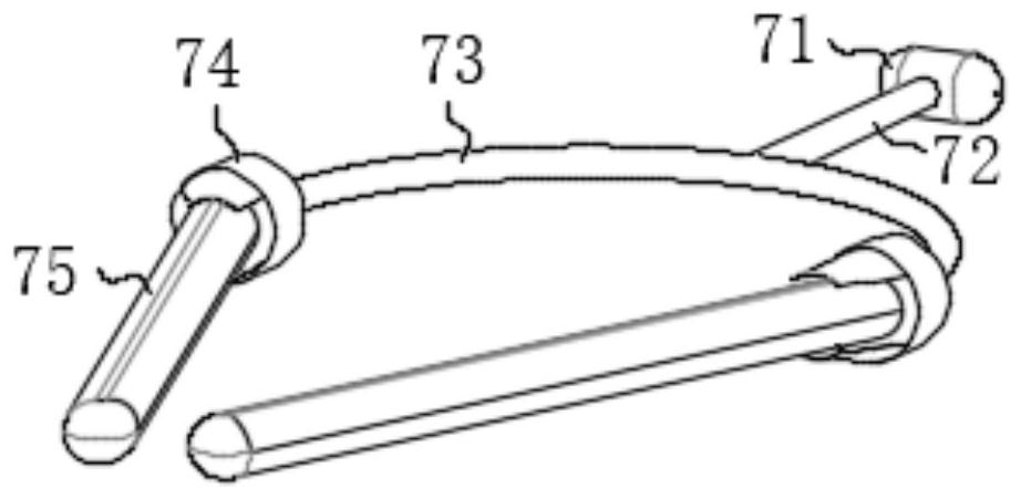
The invention belongs to the field of power distribution networks, and particularly relates to a power distribution network fault detection device, which comprises a handle, wherein a contact plate is arranged at the top of the handle, the top of the handle is fixedly connected with the bottom of the contact plate, contact blocks are evenly arranged at the top of the contact plate, the top of the contact plate is fixedly connected with the bottoms of the contact blocks, fastening mechanisms are evenly arranged at the two ends of the contact plate, the bottoms of the fastening mechanisms are fixedly connected with the inner wall of the contact plate, the fastening mechanism comprises a storage ring, contraction rings are symmetrically arranged at the two ends of the storage ring, the right end of the storage ring is movably connected with the bottoms of the contraction rings, an extrusion mechanism is arranged at the top of the contraction ring, the top of the contraction ring is fixedly connected with the right end of the extrusion mechanism, the extrusion mechanism comprises a movable shaft, a movable rod is arranged at the left end of the movable shaft, the left end of the movable shaft is fixedly connected with the right end of the movable rod, and a limiting ring is arranged at the left end of the movable rod.

Description

technical field [0001] The invention belongs to the field of distribution network, in particular to a distribution network fault detection device. Background technique [0002] In the process of power transmission, in order to ensure the normal operation of the transmission, it is often necessary to carry out fault inspection on the power distribution network. When the electric power is repaired, it is necessary to use a fault detection device, and it is often necessary to clamp the circuit with a clip to detect the fault. The existing The adjustment of the maintenance clip is small, the applicability is poor, and the clamping of the circuit line is unstable, resulting in errors in the detection results, which not only wastes the time of the maintenance workers, but also affects work efficiency, and the instability when clamping will lead to serious problems. To deal with safety accidents, a distribution network fault detection device is first proposed to solve the above-men...

Claims


Application Information

Patent Timeline
Patent Type & Authority Applications(China)
IPC IPC(8): G01R31/08
CPCG01R31/08Y04S10/52
Inventor 谭文文
Owner 谭文文
Learn More