Fixed-focus camera module and its manufacturing method

A technology of a camera module and a manufacturing method, which is applied in the directions of image communication, TV, color TV components, etc., can solve the problems of lowering the imaging quality of fixed-focus camera modules and limiting fixed-focus camera modules, etc.

Active Publication Date: 2022-07-19
NINGBO SUNNY OPOTECH CO LTD
View PDF6 Cites 0 Cited by
  • Summary
  • Abstract
  • Description
  • Claims
  • Application Information

AI Technical Summary

Problems solved by technology

The setting of the lens barrel 34P limits the size of the fixed-focus camera module, and even becomes a technical bottleneck restricting the development of the fixed-focus camera module
In addition, since the optical lens 20P is installed inside the lens barrel 34P, when installing the optical lens 20P and the lens barrel 34P or adjusting the position of the optical lens relative to the lens barrel 34P to In the process of realizing the focusing of the fixed-focus camera module, the outer surface of the optical lens 20P and the inner surface of the lens barrel 34P will cause friction between the outer surface of the optical lens 20P and the inner surface of the lens barrel 34P. The inner surface of the 34P produces some particles and other pollutants, which will be retained inside the fixed-focus camera module. Even after the fixed-focus camera module is packaged, these particles and other pollutants cannot be removed. Take it out, with the passage of time and the impact of the outside world on the fixed-focus camera module, some particles and other pollutants will enter the optical path of the optical lens 20P, and can form images on the photosensitive element 10P, so that Traveling that causes dirty spots will reduce the imaging quality of the fixed-focus camera module

Method used


Image

  • Fixed-focus camera module and its manufacturing method
  • Fixed-focus camera module and its manufacturing method
  • Fixed-focus camera module and its manufacturing method

Examples


Embodiment Construction

[0054] The following description serves to disclose the invention to enable those skilled in the art to practice the invention. The preferred embodiments described below are given by way of example only, and other obvious modifications will occur to those skilled in the art. The basic principles of the invention defined in the following description may be applied to other embodiments, variations, improvements, equivalents, and other technical solutions without departing from the spirit and scope of the invention.

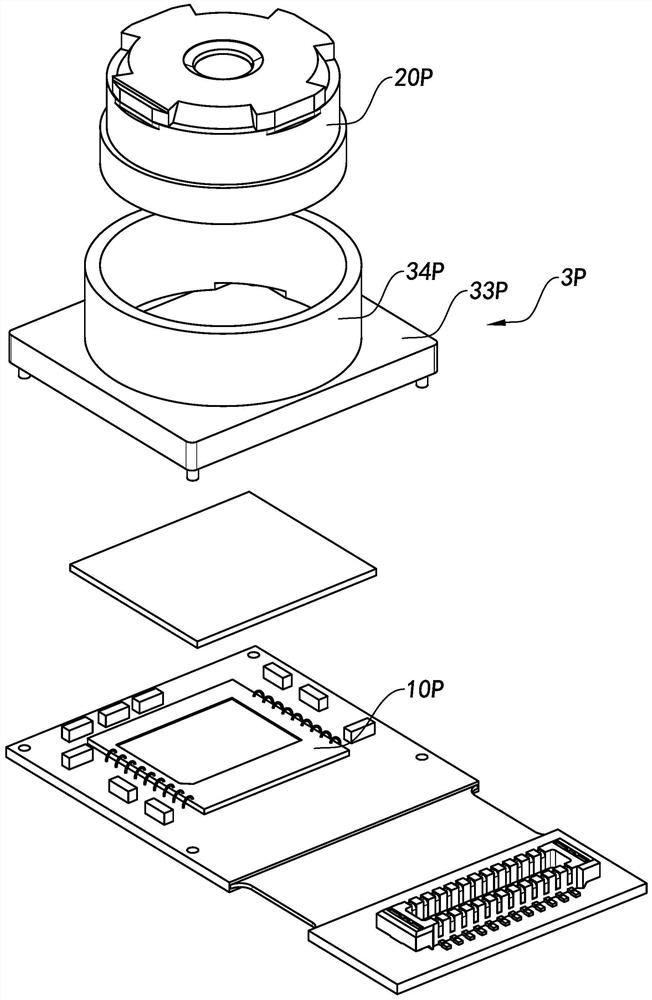
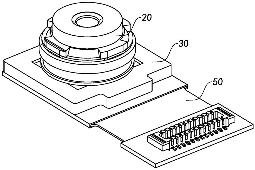
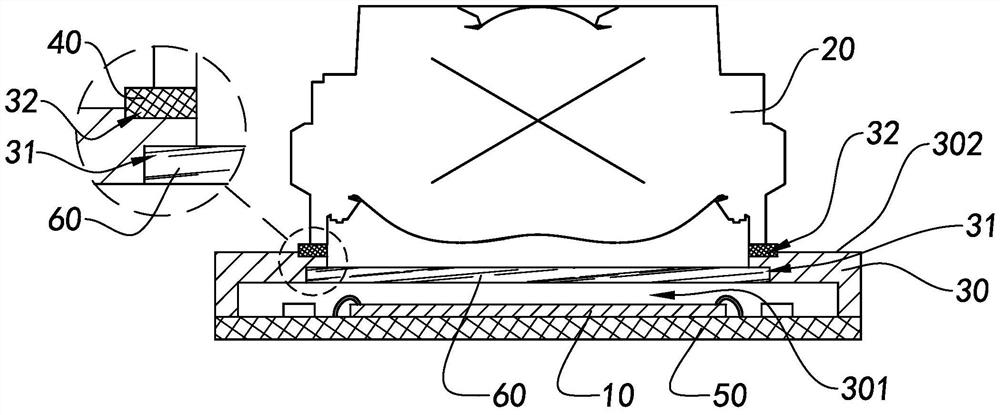
[0055] With reference to the accompanying drawings of the description of the present invention figure 2 and image 3 , according to a preferred embodiment of the present invention, a fixed-focus camera module is illustrated, wherein the fixed-focus camera module includes a photosensitive element 10, an optical lens 20 and a lens holder 30, wherein the optical lens 20 is It is packaged on the top end 302 of the lens holder 30 , a light-passing hole 301 is formed i...


PUM


Abstract

The present invention provides a fixed-focus camera module and a manufacturing method thereof, wherein the fixed-focus camera module includes a photosensitive chip, an optical lens and a lens holder, wherein the optical lens is directly packaged in the lens holder, and the The optical lens is kept in the photosensitive path of the photosensitive chip. In this way, the size and manufacturing cost of the fixed-focus camera module can be effectively reduced, so as to improve the product competitiveness of the fixed-focus camera module.

Description

technical field [0001] The invention relates to the field of optical imaging, in particular to a fixed-focus camera module and a manufacturing method thereof. Background technique [0002] With the rapid development of science and technology and the continuous improvement of people's economic level, smart phones, tablet computers, portable electronic devices and related technologies have developed rapidly. Among them, the camera module used to help users shoot images has become a One of the standard configurations of portable electronic devices. Usually, in order to facilitate the user to take selfies or make video calls through the portable electronic device, the portable electronic device is configured with a front camera module. Since the fixed-focus camera module does not need to reserve a space for focusing adjustment once it is configured in the portable electronic device, in order to control the size of the portable electronic device, the fixed-focus camera module ha...

Claims


Application Information

Patent Timeline
Patent Type & Authority Patents(China)
IPC IPC(8): H04N5/225
Inventor 陈振宇张百成苏小娟
Owner NINGBO SUNNY OPOTECH CO LTD
Why Eureka
Try Eureka