Water stop belt and deformation joint waterproof structure

A technology of waterproof structures and waterstops, applied in underwater structures, infrastructure engineering, water conservancy projects, etc., can solve problems such as insufficient extensiveness, weak tensile and twisting deformation capabilities, and corrosion of steel edges. Achieve high elasticity, avoid fatigue aging and prolong service life

Inactive Publication Date: 2018-01-09
CHINA 19TH METALLURGICAL CORP
View PDF6 Cites 7 Cited by
  • Summary
  • Abstract
  • Description
  • Claims
  • Application Information

AI Technical Summary

Problems solved by technology

The rubber itself is not strong in resistance to stretching and twisting. Long-term stretching and deformation will cause permanent fatigue deformation, and the elasticity and plasticity will deteriorate. Coupled with natural aging, it is easy to crack and break, and loses the waterproof effect.
[0006] 2. High requirements for construction control
[0008] 3. High risk of leakage
[0009] Due to the difference in thermal expansion coefficient between the rubber and concrete of the traditional mid-buried rubber waterstop, micro gaps will appear over time. The improved steel edge rubber waterstop adds steel edges, and although it is more tightly bonded to the concrete, the rubber There will still be micro gaps on the contact surface with the concrete, and the intrusion of water vapor will cause corrosion to the steel edge, which will al...

Method used


Image

  • Water stop belt and deformation joint waterproof structure
  • Water stop belt and deformation joint waterproof structure
  • Water stop belt and deformation joint waterproof structure

Examples


Embodiment Construction

[0034] The present invention is further described below.

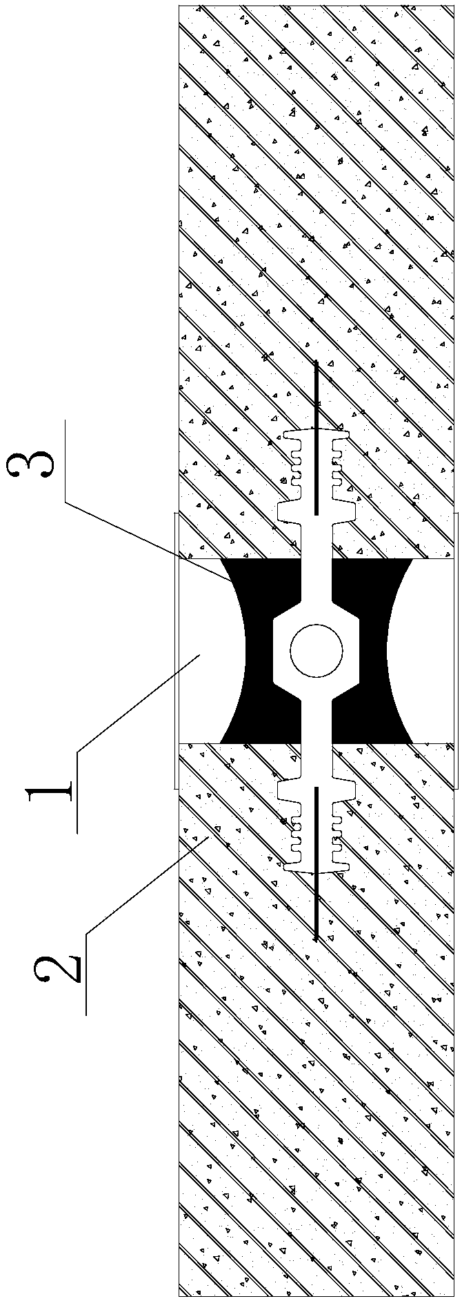
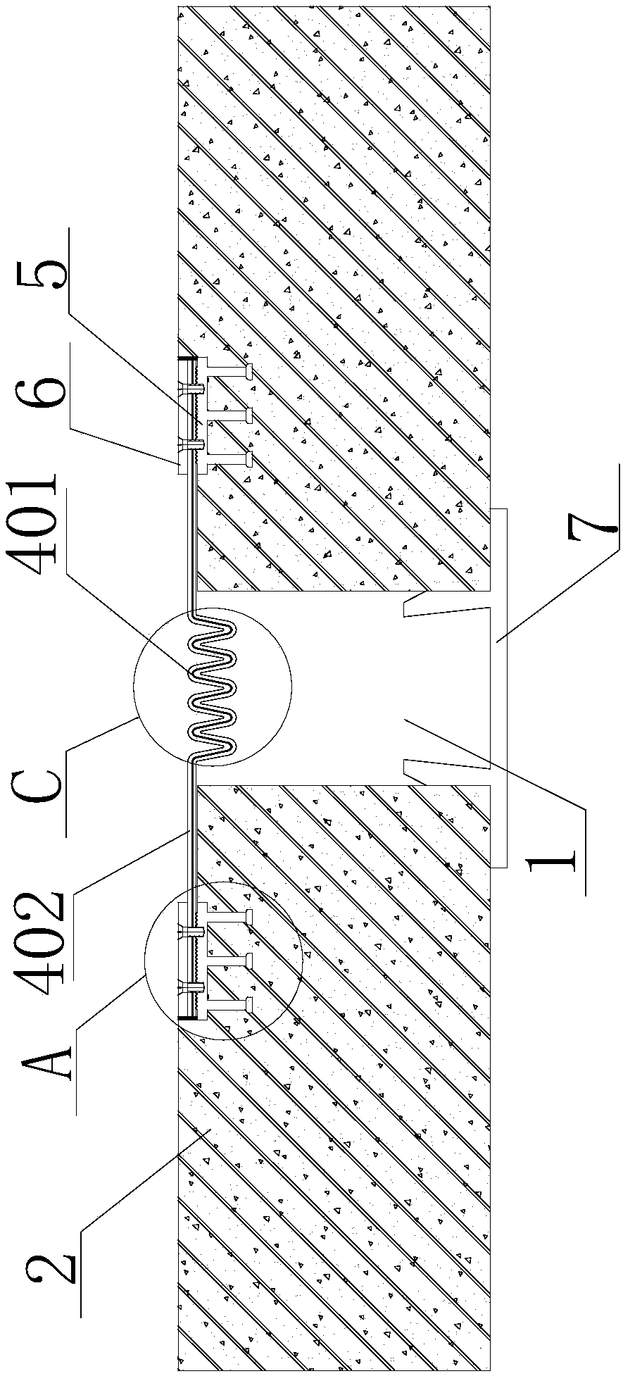
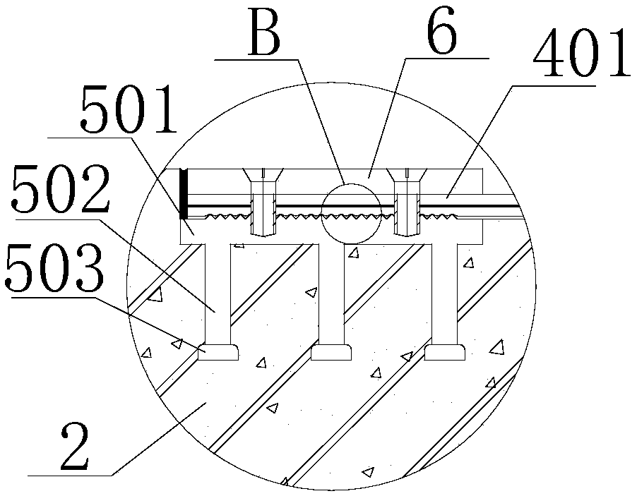
[0035] The waterstop disclosed in the present invention includes a waterproof layer 401 and an inner lining layer 402 along the thickness direction, and at least one side of the inner lining layer 402 is covered with the waterproof layer 401; along the width direction, it includes a stretchable part 403 in the middle and The connecting portion 404 located on both sides, the stretchable portion 403 is folded to form a stretchable structure, and the strength and rigidity of the material of the inner lining layer 402 are greater than that of the waterproof layer 401 .

[0036] Such as figure 2 As shown, when using the waterstop, connect the connecting parts 404 on both sides to the concrete structures 2 on both sides of the deformation joint 1, so that the waterstop covers the entire deformation joint 1 to achieve waterproof effect; the expansion and contraction of the waterstop The part 403 is located between the concr...


PUM


Abstract

The invention relates to the field of building waterproofing and discloses a water stop belt and a pipe gallery deformation joint waterproof structure. The water stop belt comprises a waterproof layerand a lining layer in the thickness direction and an extending-and-retracting portion and connection portions in the width direction, wherein the waterproof layer is arranged on one or more faces ofthe lining layer in a covering manner; and the extending-and-retracting portion is located in the middle, and the connection portions are located at the two sides. The extending-and-retracting portionis folded, so that an extendable-and-retractable structure is formed. The strength and rigidity of the material of the lining layer are greater than those of the waterproof layer. The waterproof layer and the lining layer are compounded in the water stop belt; the stress generated by the vast majority of self weight on the extending-and-retracting portion of the water stop belt is borne by the lining layer, and thus the fatigue and aging problems of the waterproof layer are avoided to a great extent; the service life of the water stop belt can be prolonged; by means of physical deformation ofthe extending-and-retracting portion of the water stop belt, deformation, caused by differential settlement, of a pipe gallery can be resisted against; after deformation is generated, the strength, sealing performance and material performance are not affected; the waterproof effect can be achieved better; and the water stop belt is particularly applicable to deformation joint waterproofing of thecomprehensive pipe gallery.

Description

technical field [0001] The invention relates to the field of building waterproofing, in particular to a waterproof structure for deformation joints of waterstops and pipe galleries. Background technique [0002] Whether it is tunnels, bridges, embankments, roads, buildings or the houses we live in, waterproofing cannot be ignored, especially in the construction of underground comprehensive pipe corridors, waterproofing is an essential process. The design service life of the general pipe gallery is 100 years, which can be called a century-old project in the true sense, 30 years longer than the service life of the housing construction project. How to do a good job of waterproofing the deformation joints of the pipe gallery for a long time is of great significance to the long-term use of the urban underground comprehensive pipe gallery. [0003] Waterstops are currently the most widely used waterproofing facilities for engineering gaps. Commonly used waterstops include traditi...

Claims


Application Information

Patent Timeline
IPC IPC(8): E02D29/16E02D31/02E02D29/045
Inventor 苏光明
Owner CHINA 19TH METALLURGICAL CORP
Why Eureka
Try Eureka