Weir gate limiting device, catch basin and weir gate provided with limiting device

A technology of limiting devices and intercepting wells, which is applied in water supply devices, waterway systems, buildings, etc., can solve problems such as environmental restrictions on the use of floating box weir gates, obstacles to upstream water flow to downstream, and increased manufacturing costs, achieving a wide range of applications , Avoid urban waterlogging, prevent urban waterlogging effects

Inactive Publication Date: 2018-01-09
WUHAN SHENGYU DRAINING SYST
View PDF8 Cites 0 Cited by
  • Summary
  • Abstract
  • Description
  • Claims
  • Application Information

AI Technical Summary

Problems solved by technology

[0004] Since the specifications of the existing floating box-type weir gates are mostly fixed, and the operating environments are often different, there are often the following problems: when the downstream water level rises to a certain height, the gate leaves of the above-mentioned interception wells will rotate completely, and the gate leaves in the vertical At this time, the downstream water level is still a certain height from the top of the door leaf. When the upstream water body needs to pass through the water to the downstream, because the opening of the door leaf in the vertical state is too large, only when the upstream water level exceeds the top of the door leaf can it be opened. It can pass through water, so that the floating box-type weir gate can prevent backwashing and at the same time hinder the flow of upstream water to the downstream, causing urban waterlogging. If the floating box-type weir gate with different specifications is designed according to different environments, the manufacturing cost will increase. The use environment of the box weir gate is limited

Method used


Image

  • Weir gate limiting device, catch basin and weir gate provided with limiting device
  • Weir gate limiting device, catch basin and weir gate provided with limiting device

Examples


Embodiment 1

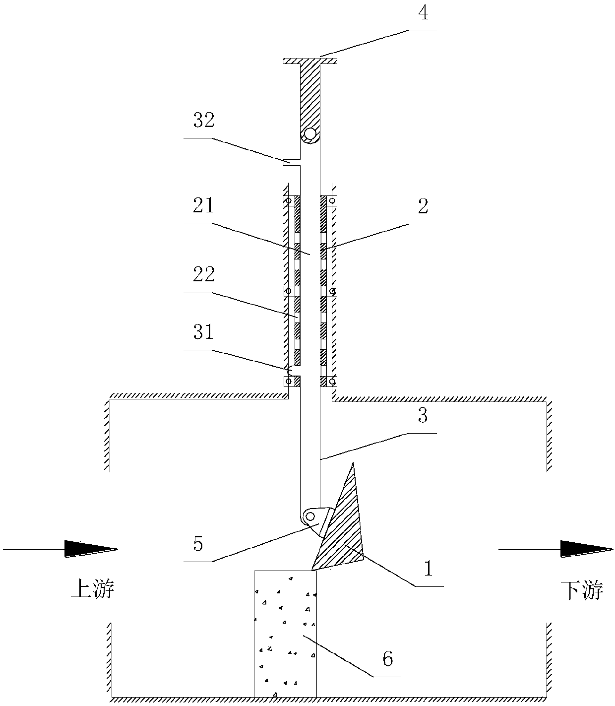
[0035] see figure 1 As shown, the embodiment of the present invention provides a weir gate limiting device, which is used to limit the opening of the buoyant tank type weir gate 1 , and includes a sleeve 2 and a rod 3 .

[0036] The sleeve 2 is provided with a first connection part; the rod part 3 is slidably arranged in the sleeve 2, and the rod part 3 is provided with a second connection part, and the first connection part and the second connection part are used together so that the rod part 3 can be It is clamped on at least one position of the sleeve 2, and the end of the rod 3 protrudes from the sleeve.

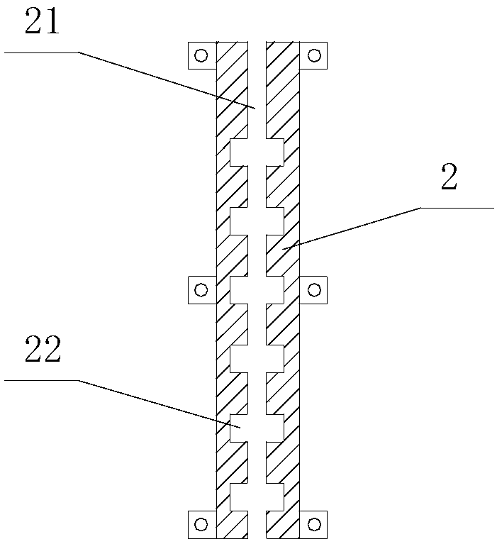
[0037] see figure 2 As shown, the first connecting part includes a chute 21 and a number of limiting grooves 22 arranged at intervals along the length direction of the chute 21 , the chute 21 is arranged axially along the sleeve 2 , and the limiting groove 22 communicates with the chute 21 ; The second connecting part includes a protrusion 31 arranged on the rod 3, th...

Embodiment 2

[0052] The difference between the second embodiment and the first embodiment is that the second connecting part includes a chute 21 and a number of limit grooves 22 arranged at intervals along the length direction of the chute 21, the chute 21 is arranged axially along the rod 3, and the limit The groove 22 communicates with the sliding groove 21; the first connecting part includes a protrusion 31 arranged in the sleeve 2, the protrusion 31 can move in the sliding groove 21, and the protrusion 31 is clamped in the limiting groove 22 , the ends of the rods 3 all protrude from the sleeve 2.

Embodiment 3

[0054] The difference between the third embodiment and the first embodiment is that the sleeve 2 and the rod 3 are used in conjunction with threads, the first connection part is an internal thread provided on the inner wall of the sleeve, and the second connection part is an external thread matched with the internal thread. screw thread, the rod 3 can move helically in the sleeve 2, and when the rod 3 and the sleeve 2 are screwed together, the end of the rod 3 protrudes from the sleeve 2.


PUM


Abstract

The invention discloses a weir gate limiting device, and relates to the technical field of the drainage system. The weir gate limiting device comprises a sleeve and a rod component. The sleeve is provided with a first connecting part. The rod component is installed in the sleeve. The rod component is provided with a second connecting part. The first connecting part is matched with the second connecting part, so the rod component can be locked on at least one position of the sleeve, and the tail end of the rod component is stretched out from the sleeve. The provided weir gate limiting device iscapable of preventing the backward flow of the floating-pontoon-type weir gate, and preventing the urban inland inundation because upstream water is not affected to be flowed to the downstream. The application range is wide.

Description

technical field [0001] The invention relates to the field of drainage systems, in particular to a weir gate limiting device, an interception well and a weir gate equipped with the limiting device. Background technique [0002] Interception wells have been widely used in the combined pipeline system in urban drainage projects in my country. When the downstream water level rises above the elevation of the upstream pipe top, it will cause backflow of downstream water, resulting in backflow of water exceeding the interception capacity into the interception sewage pipe network, causing impact loads on the terminal sewage plant. [0003] In the Chinese utility model patent specification CN201620125125.1, an interception well with a check function is disclosed. A fixed weir gate is arranged in the well body near the mouth of the water outlet pipe, and a buoyancy tank is arranged on the top of the side of the fixed weir gate near the water outlet pipe. The floating box weir gate co...

Claims


Application Information

Patent Timeline
Patent Type & Authority Applications(China)
IPC IPC(8): E03F7/04
Inventor 庞尚志周智勇
Owner WUHAN SHENGYU DRAINING SYST
Why Eureka
Try Eureka