Valve and valve rod booster

A technology of booster and valve stem, applied in valve details, valve device, valve operation/release device, etc., can solve problems such as hidden danger of industrial valve safety use, device slippage, valve handwheel and external device fixed connection, etc. Solve the effect of assisting the opening of damaged valves and avoiding slippage

Active Publication Date: 2018-01-09
WUHAN INSTITUTE OF TECHNOLOGY
View PDF6 Cites 1 Cited by
  • Summary
  • Abstract
  • Description
  • Claims
  • Application Information

AI Technical Summary

Problems solved by technology

[0002] Various valves on pipelines and equipment will occur during use due to the harsh operating environment, such as corrosion of the metal surface or interior of the valve under complex working conditions such as the atmosphere or solution, or Improper use methods such as impact or long lever forceful operation lead to damage to the handwheel, handwheel fall off, etc. When these situations occur, it will further cause the valve to be difficult to open, and in more serious cases, the valve cannot be opened, which will seriously affect the flow of the fluid. This has brought hidden dangers to the safe use of industrial valves, and has affected the safe production and economic benefits of various departments
[0003] The existing device for assisting the valve mainly limits the shape and position of the valve handwheel by designing a certain structural form, and does not make a good connection between the valve handwheel and the external device. During the process of applying external force , which may cause the device to slip, causing hidden dangers to equipment or personal safety
In addition, none of these devices can be applied to damaged valves, such as the valve handwheel falling off and only the valve stem remaining

Method used


Image

  • Valve and valve rod booster
  • Valve and valve rod booster
  • Valve and valve rod booster

Examples


Embodiment Construction

[0027] In order to have a clearer understanding of the technical features, purposes and effects of the present invention, the specific implementation manners of the present invention will now be described in detail with reference to the accompanying drawings.

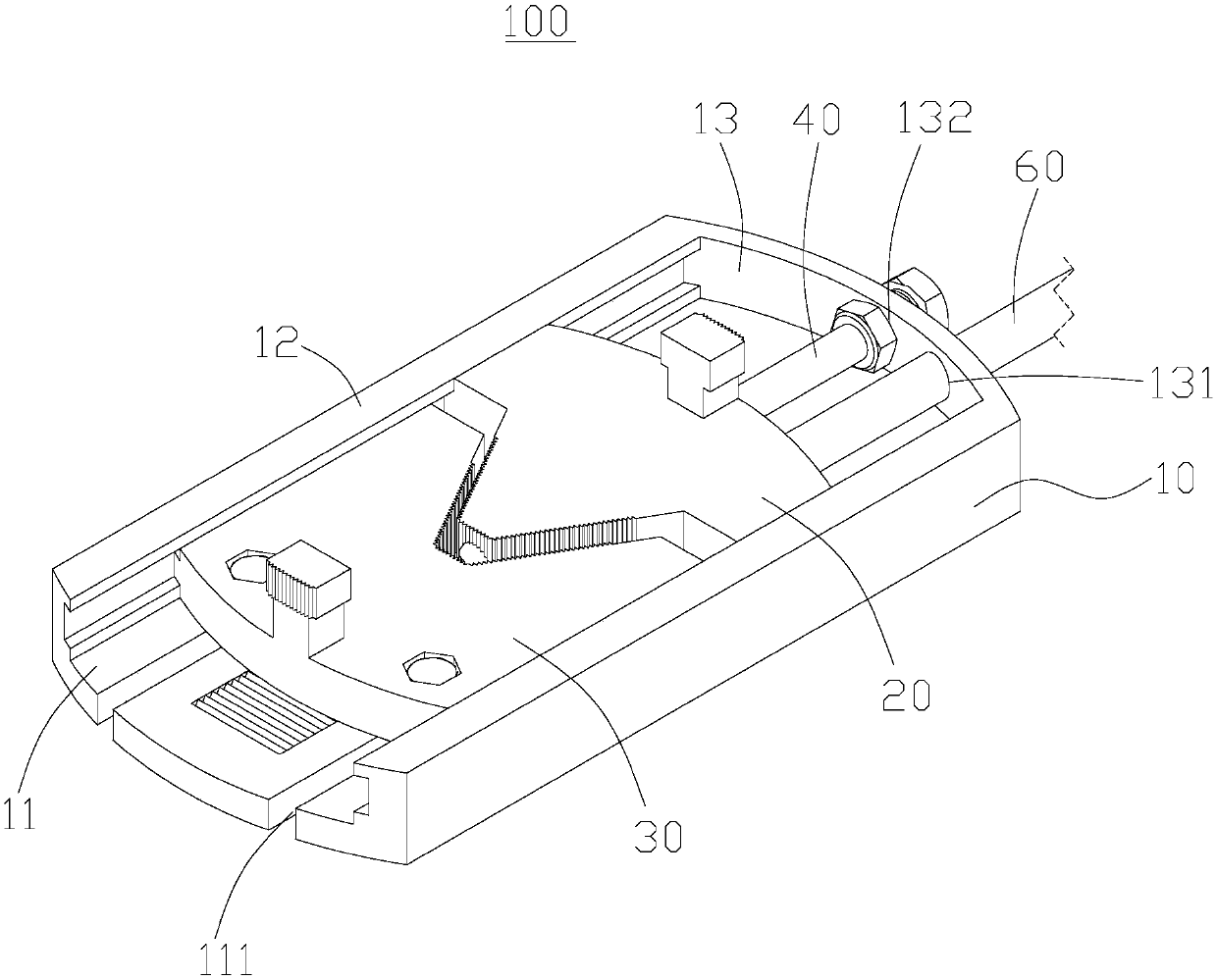
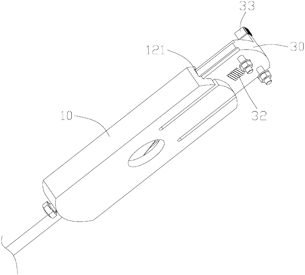
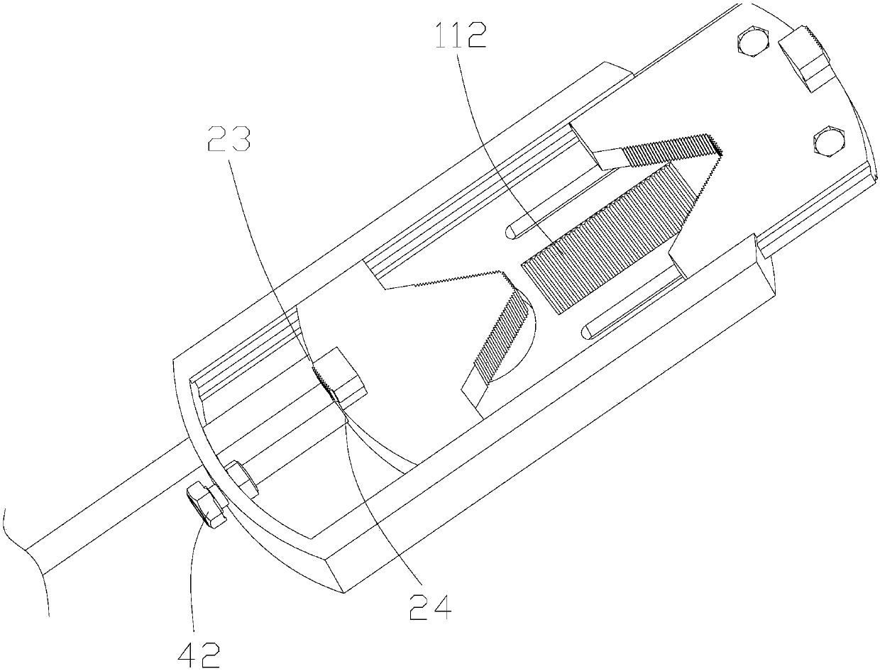
[0028] Such as Figure 1-4 As shown, it is a valve stem booster 100 of a preferred embodiment of the present invention, including a housing 10, a first fixing member 20, a second fixing member 30 and a booster rod 60, the housing 10 includes a bottom plate 11, and the first fixing member The piece 20 and the second fixing piece 30 are slidably installed on the bottom plate 11 in turn, and the first fixing piece 20 and the second fixing piece 30 are respectively provided with first clamping teeth 21 and second clamping teeth 31 with matching shapes on opposite sides of the second fixing piece 30. A clamping tooth 21 and a second clamping tooth 31 cooperate to clamp the valve stem 301; the housing 10 is provided with a fi...


PUM


Abstract

The invention relates to a valve and valve rod booster. The valve and valve rod booster comprises a shell, a first fixing part, a second fixing part and a power rod. The shell comprises a bottom plate. The first fixing part and the second fixing part are slidably mounted on the bottom plate in sequence. The opposite sides of the first fixing part and the second fixing part are correspondingly provided with first clamping teeth and second clamping teeth, wherein the shapes of the first clamping teeth and the second clamping teeth are matched. The first clamp teeth and the second clamping teethare matched to clamp a valve rod. A first limiting hole used for being penetrated by the power rod is formed in the shell. The valve and valve rod booster has many functions, besides realization of the function of full opening of valve power, the problem of power opening of a damaged valve is solved, in the opening process, fixing and clamping of a valve handwheel or the valve rod can be achieved,and hidden dangers for equipment or personal safety caused by slippage of a device in the opening process is avoided; and through a trapezoidal thread transmission mechanism, the clamp teeth spacingis adjusted, and the purpose of power opening of valve handwheels of different diameters is achieved.

Description

technical field [0001] The invention relates to the technical field of pressure pipeline equipment, in particular to a valve stem booster. Background technique [0002] Various valves on pipelines and equipment will occur during use due to the harsh operating environment, such as corrosion of the metal surface or interior of the valve under complex working conditions such as the atmosphere or solution, or Improper use methods such as impact or long lever forceful operation lead to damage to the handwheel, handwheel fall off, etc. When these situations occur, it will further cause the valve to be difficult to open, and in more serious cases, the valve cannot be opened, which will seriously affect the flow of the fluid. This has brought hidden dangers to the safe use of industrial valves, and has affected the safe production and economic benefits of various departments. [0003] The existing device for assisting the valve mainly limits the shape and position of the valve hand...

Claims


Application Information

Patent Timeline
Patent Type & Authority Applications(China)
IPC IPC(8): F16K31/60B25B33/00
Inventor 程俊文舒安庆丁克勤龚雪茹张宏鹏
Owner WUHAN INSTITUTE OF TECHNOLOGY
Why Eureka
Try Eureka