Bridge monitoring equipment convenient to debug

A technology for monitoring equipment and bridges, which is applied in the direction of mechanical equipment, supporting machines, machine platforms/supports, etc. It can solve the problems of slowing down the installation progress, affecting the installation efficiency, and difficult operation, and achieves improved installation efficiency, simple structure, and reduced labor. The effect of the operation

Inactive Publication Date: 2018-01-09
叶丛杰
View PDF6 Cites 5 Cited by
  • Summary
  • Abstract
  • Description
  • Claims
  • Application Information

AI Technical Summary

Problems solved by technology

[0002] At present, on some bridges, monitoring equipment for monitoring and shooting illegal vehicles can often be seen. However, these monitoring equipment need to be adjusted for their orientation and angle before installation and fixing. In the prior art, the adjustment of orientation and angle is done manually. The operation is completed, so the operation is difficult, which seriously affects the installation efficiency. At the same time, if the basic road changes in the later period, when the monitoring equipment needs to be debugged for the second time, it needs to be unfixed first, and then re-adjust the orientation and angle before fixing. The process is more cumbersome , time-consuming and labor-intensive, slowing down the installation progress

Method used


Image

  • Bridge monitoring equipment convenient to debug
  • Bridge monitoring equipment convenient to debug
  • Bridge monitoring equipment convenient to debug

Examples


Embodiment Construction

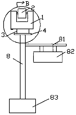
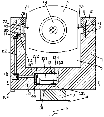
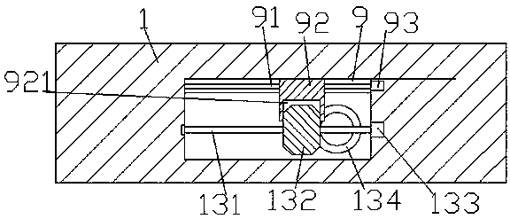
[0023] Such as Figure 1-Figure 6 As shown, a bridge monitoring device convenient for debugging of the present invention includes a frame 1 with a hollow mechanism 5 on the inner top and a frame seat 3 that is connected to the bottom of the frame 1 in operation and cooperation. A fixed plate 2 is provided, the front end of the fixed plate 2 is provided with a monitoring probe 24, the left and right sides of the fixed plate 2 are respectively provided with a first revolving pin shaft 21 and a second revolving pin shaft 22, and the first revolving pin A first sliding block 72 is connected to the left side of the shaft 21 in operation. A mouth groove 73 is provided in the first sliding block 72 . The third toothed wheel 23 that is fixedly connected, the tail of the right side of the second revolving pin shaft 22 is running and connected with a second sliding block 71, and the top of the inner wall on the left and right sides of the hollow mechanism 5 is correspondingly provided w...


PUM


Abstract

The invention discloses a bridge monitoring equipment convenient to debug. The bridge monitoring equipment convenient to debug comprises a rack, a rack base, a hollow mechanism is arranged in the inner top of the rack, the rack base is in operating fit connection with the bottom of the rack, the hollow mechanism is internally provided with a fixing plate, and a monitoring probe is arranged on thefront end face of the fixing plate; a first rotating pin shaft and a second rotating pin shaft are arranged on the left side and the right side of the fixing plate correspondingly, a first sliding block is in operating fit connection with the tail part of the left side of the first rotating pin shaft, and the first sliding block is internally provided with an opening part groove, and a third toothed wheel which is fixedly connected with the first rotating pin shaft is arranged in the opening part groove; a second sliding block is in operating fit connection with the tail part of the right sideof the second rotating pin shaft, placing grooves are correspondingly formed in the tops of the inner walls of the left side and the right side of the hollow mechanism, and a first accommodating cavity is formed in rack and is located on the side, deviated from the hollow mechanism, the left placing groove; and a second accommodating cavity is formed in the rack below the first accommodating cavity, a third accommodating cavity is formed in the rack on the right side of the second accommodating cavity , a rod shaft which is arranged in a left-right extending mode is arranged in the third accommodating cavity, and the right side end of the rod shaft is connected with a first electric rotating machine.

Description

technical field [0001] The invention relates to the technical field of bridge facilities, in particular to bridge monitoring equipment which is convenient for debugging. Background technique [0002] At present, on some bridges, monitoring equipment for monitoring and shooting illegal vehicles can often be seen. However, these monitoring equipment need to be adjusted for their orientation and angle before installation and fixing. In the prior art, the adjustment of orientation and angle is done manually. The operation is completed, so the operation is difficult, which seriously affects the installation efficiency. At the same time, if the basic road changes in the later period, when the monitoring equipment needs to be debugged for the second time, it needs to be unfixed first, and then re-adjust the orientation and angle before fixing. The process is more cumbersome , time-consuming and labor-intensive, slowing down the installation progress. Contents of the invention ...

Claims


Application Information

Patent Timeline
IPC IPC(8): F16M11/18F16M11/06
Inventor 叶丛杰
Owner 叶丛杰
Why Eureka
Try Eureka