Fresh air system and control method thereof

A technology of a fresh air system and control method, which is applied in ventilation systems, air conditioning systems, heating methods, etc., can solve the problems of poor dehumidification efficiency of fresh air fans, inability to provide fresh air, and large temperature differences, and reduce energy consumption throughout the year. The effect of improving power saving efficiency and expanding the seasonal range

Active Publication Date: 2018-01-09
GD MIDEA HEATING & VENTILATING EQUIP CO LTD +1
View PDF7 Cites 13 Cited by
  • Summary
  • Abstract
  • Description
  • Claims
  • Application Information

AI Technical Summary

Problems solved by technology

Method 1 is the current mainstream solution. However, when the outdoor temperature is very high or very low, for example, when the outdoor temperature is higher than 40 degrees or lower than -5 degrees, the efficiency of fresh air will be very low, and it will not even be able to provide fresh air; method 2 is through Air convection exchanges heat, the fresh air efficiency is low, and it is greatly affected by the indoor and outdoor temperature difference; method 3 can appropriately improve the fresh air efficiency of method 1, but it is still greatly affected by the outdoor temperature; method 4 is affected by the outlet water temperature, and the dehumidification of the fresh air fan Poor efficiency

Method used


Image

  • Fresh air system and control method thereof
  • Fresh air system and control method thereof
  • Fresh air system and control method thereof

Examples


Embodiment Construction

[0034]Embodiments of the present invention are described in detail below, examples of which are shown in the drawings, wherein the same or similar reference numerals designate the same or similar elements or elements having the same or similar functions throughout. The embodiments described below by referring to the figures are exemplary and are intended to explain the present invention and should not be construed as limiting the present invention.

[0035] The fresh air system according to the embodiment of the first aspect of the present invention will be described below with reference to the accompanying drawings.

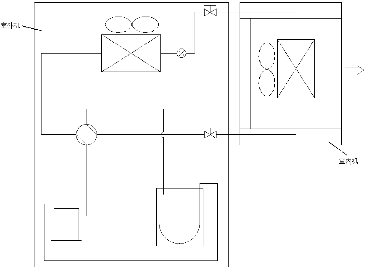
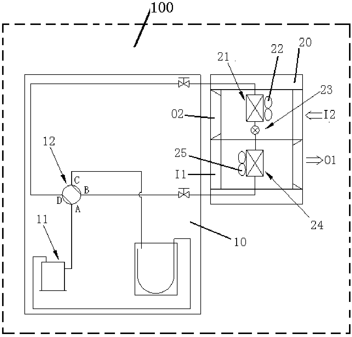
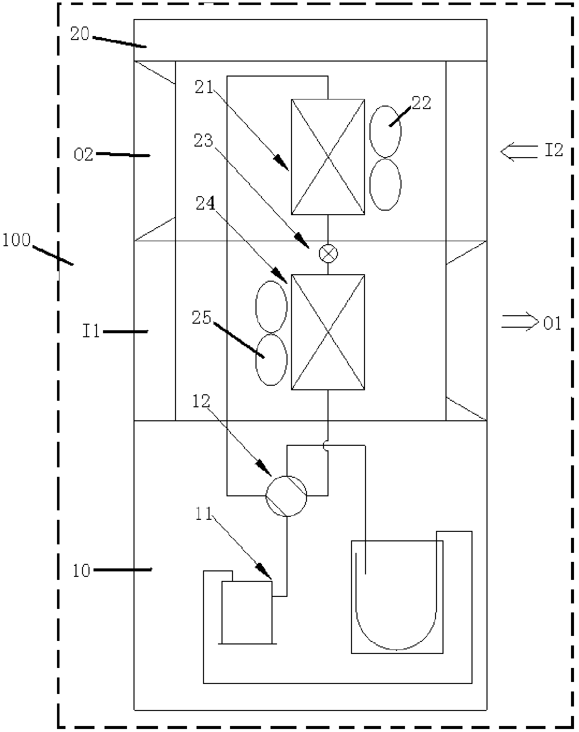
[0036] figure 2 is a block diagram of a fresh air system according to an embodiment of the present invention, such as figure 2 As shown, the fresh air system 100 of the embodiment of the present invention includes a refrigerant delivery device 10, an indoor unit 20 and a controller (not shown in the figure).

[0037] Wherein, the refrigerant delivery device ...


PUM


Abstract

The invention discloses a fresh air system and a control method thereof. The fresh air system comprises a refrigerant conveying device, an indoor unit and a controller. The refrigerant conveying device comprises a compressor and a four-way valve. The indoor unit comprises a fresh air inlet, a fresh air outlet, an exhaust air inlet, an exhaust air outlet, a first heat exchanger, an exhaust fan, a throttling device, a second heat exchanger and a forced draught fan, wherein one end of the throttling device is connected with one end of the first heat exchanger, and the other end of the throttlingdevice is connected with one end of the second heat exchanger. The controller controls the exhaust fan, the forced draught fan, the compressor and the four-way valve according to a selected operationmode and set target parameters, outdoor fresh air entering the system from the fresh air inlet flows through the second heat exchanger and the forced draught fan to be fed into a room through the fresh air outlet, and indoor air entering the system from the exhaust air inlet flows through the first heat exchanger and the exhaust fan to be exhausted out of the room through the exhaust air outlet. The fresh air efficiency can be improved, energy consumption is reduced, and the using seasons of the system are extended.

Description

technical field [0001] The invention belongs to the technical field of air environment conditioning equipment, and in particular relates to a fresh air system and a control method for the fresh air system. Background technique [0002] At present, there are mainly the following ways to realize the fresh air system: Mode 1, such as figure 1 As shown, the fresh air solution is provided by using the traditional air conditioner of the indoor unit and the outdoor unit; Method 2, the fresh air solution is provided by a full heat exchanger; Method 3, the superposition of methods 1 and 2 is used to provide fresh air; , Provide fresh air solutions based on the end of the water machine. Method 1 is the current mainstream solution. However, when the outdoor temperature is very high or very low, for example, when the outdoor temperature is higher than 40 degrees or lower than -5 degrees, the efficiency of fresh air will be very low, and it will not even be able to provide fresh air; me...

Claims


Application Information

Patent Timeline
Patent Type & Authority Applications(China)
IPC IPC(8): F24F1/00F24F7/007F24F11/64F24F11/65F24F11/77F24F13/30
CPCY02B30/70
Inventor 熊美兵许永锋马熙华任林行梁泽坤
Owner GD MIDEA HEATING & VENTILATING EQUIP CO LTD
Why Eureka
Try Eureka