Reduction furnace

A reduction furnace and furnace tube technology, applied in the field of reduction furnaces, can solve the problems of inconsistent distribution, reducing reduction efficiency, and prolonging reduction time.

Pending Publication Date: 2018-01-09
ADVANCED FOR MATERIALS & EQUIP
View PDF6 Cites 2 Cited by
  • Summary
  • Abstract
  • Description
  • Claims
  • Application Information

AI Technical Summary

Problems solved by technology

However, when loading boats automatically, the amount of material injected into the boats is controlled manually, which may easily lead to inconsistent distribution of materials on each boat, and the more material on the boat, the thicker the material.
Therefore, after the materials on the boats of the same batch are reduced within the same time period, the materials on the boats with less amount of materials have been completely reduced, while at th

Method used


Image

  • Reduction furnace
  • Reduction furnace
  • Reduction furnace

Examples


Embodiment Construction

[0033] In order to enable those skilled in the art to better understand the technical solutions in the present application, the technical solutions in the embodiments of the present application will be clearly and completely described below in conjunction with the drawings in the embodiments of the present application. Obviously, the described The embodiments are only some of the embodiments of the present application, but not all of them. Based on the embodiments in this application, all other embodiments obtained by persons of ordinary skill in the art without creative efforts shall fall within the scope of protection of this application.

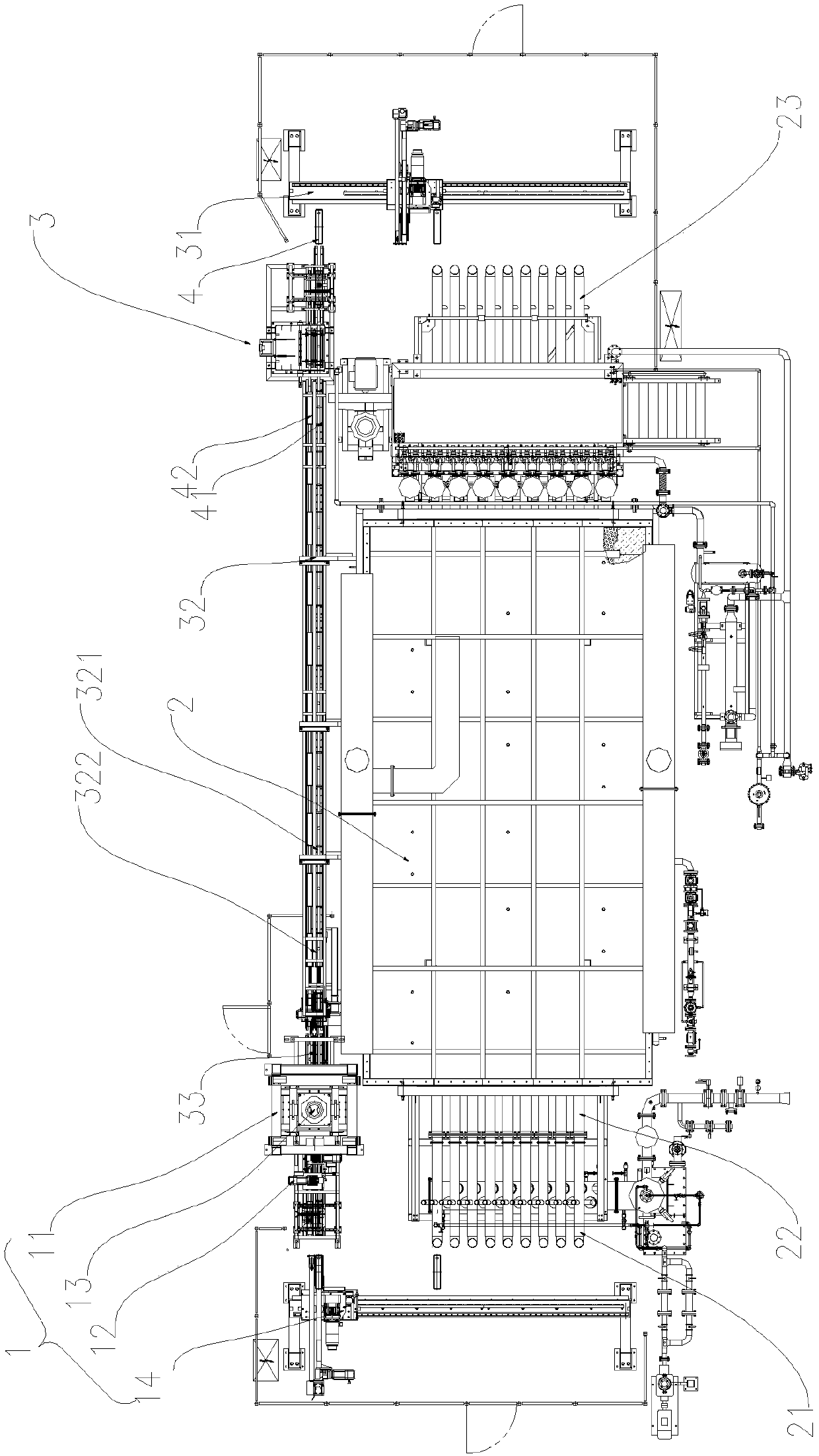
[0034] Such as figure 1 As shown, a reduction furnace provided in an embodiment of the present invention includes:

[0035] Feeding system 1, the feeding system 1 is used to feed the materials to be reduced;

[0036] Thermal reduction system 2, thermal reduction system 2 is connected with feed system 1 for reducing materials;

[0037] ...


PUM


Abstract

The invention discloses a reduction furnace. The reduction furnace comprises a feeding system, a thermal reduction system, a discharging system and boats, wherein the feeding system is used for feeding to-be-reduced materials, the thermal reduction system is connected with the feeding system and used for reducing the materials, the discharging system is connected with the thermal reduction systemand used for sending out reduced materials, and the boats are used for containing the materials which move among the feeding system, the thermal reduction system and the discharging system; and the feeding system comprises a feeding device and a material weighing device, the feeding device is connected with the thermal reduction system through the material weighing device, and the material weighing device is used for controlling the weights of the materials on the boats. According to the reduction furnace, the weights of the materials which are distributed on the boats can be automatically weighed, so that the weights of the materials on all the boats are kept consistent, and the reduction efficiency of the materials is improved.

Description

technical field [0001] The application relates to the field of metallurgical preparation equipment, in particular to a reduction furnace. Background technique [0002] The reduction and thermal decomposition of tungsten, molybdenum, cobalt, and nickel powder materials generally use pusher-type single-tube, double-tube, four-tube, fourteen-tube, fifteen-tube furnaces and other equipment. [0003] The above-mentioned equipment all adopts boat loading. With the development of automation equipment, most of the current reduction and thermal decomposition equipment for tungsten, molybdenum, cobalt, and nickel powder materials can automatically load boats. However, when the boats are loaded automatically, the amount of material injected into the boats is controlled manually, which easily leads to inconsistent distribution of materials on each boat, and the more materials on the boats, the thicker the material. Therefore, after the materials on the boats of the same batch are redu...

Claims


Application Information

Patent Timeline
IPC IPC(8): F27B9/26F27B9/38F27B9/39F27B9/30G01G19/00
Inventor 戴煜羊建高周强董尚志
Owner ADVANCED FOR MATERIALS & EQUIP
Why Eureka
Try Eureka