
Pile foundation monitoring system based on distributed fiber sensor

A distributed optical fiber, monitoring system technology, applied in instruments, measuring devices, measuring ultrasonic/sonic/infrasonic waves, etc., can solve the problems of small amount of regular monitoring data, large manpower input, inability to perform high-precision monitoring, etc., and achieve timely and accurate monitoring. Deformation information, the effect of high positioning accuracy

Pending Publication Date: 2018-01-09
必必优(深圳)科技有限公司
View PDF8 Cites 1 Cited by
  • Summary
  • Abstract
  • Description
  • Claims
  • Application Information

AI Technical Summary

Problems solved by technology

Other monitoring methods refer to special instrument monitoring, which is not only expensive but also has a very limited monitoring range
[0003] In addition, the conventional monitoring methods for domestic geological disasters are mainly through group monitoring and prevention and the on-site participation of monitoring personnel. The shortcomings are mainly manifested in 1. There are many manual operations and large manpower investment. Wireless transmission cannot be used in severe weather conditions, and the personal safety of monitoring personnel in dangerous areas cannot be guaranteed; 2. The structure of the existing geological disaster monitoring system is complex and difficult to install; 3. The data processing time is long, and the amount of regular monitoring data Small, mostly point-shaped monitoring, it is difficult to accurately describe the deformation trend of the area; 4. The detection accuracy is relatively low, and high-precision monitoring cannot be carried out. The geological disaster early warning range is too large, and it is difficult to provide good services for geological disaster decision-making

Method used


Image

  • Pile foundation monitoring system based on distributed fiber sensor
  • Pile foundation monitoring system based on distributed fiber sensor

Examples


Embodiment Construction

[0027] The following will clearly and completely describe the technical solutions in the embodiments of the present invention with reference to the accompanying drawings in the embodiments of the present invention. Obviously, the described embodiments are only some, not all, embodiments of the present invention. Based on the embodiments of the present invention, all other embodiments obtained by persons of ordinary skill in the art without creative efforts fall within the protection scope of the present invention.

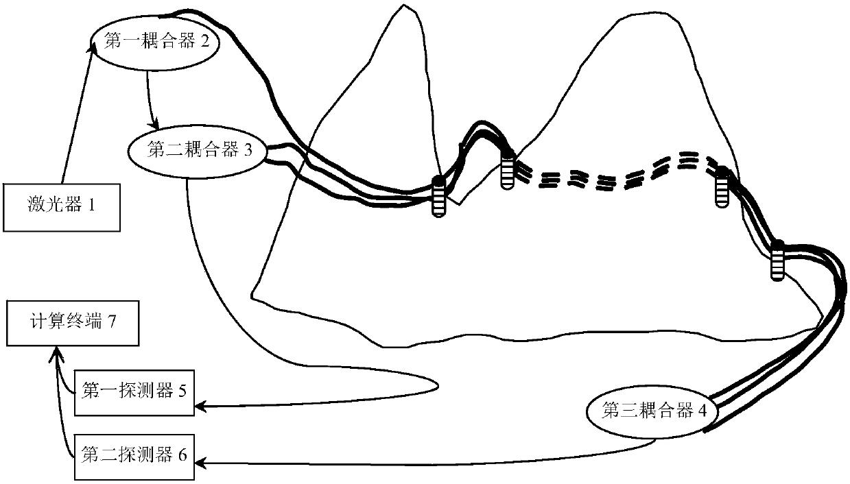
[0028] see figure 1 , is a structural schematic diagram of an embodiment of a pile foundation monitoring system based on a distributed optical fiber sensor provided by the present invention. Such as figure 1 As shown, the pile foundation monitoring system includes: a laser 1, a first coupler 2, a second coupler 3, a third coupler 4, a first detector 5, a second detector 6, a computing terminal 7 and N transmission Sensing fiber optic foundation pile, N≥1.

[002...


PUM


Abstract

The present invention discloses a pile foundation monitoring system based on a distributed fiber sensor. The system comprises a laser, a first coupler, a second coupler, a third coupler, a first detector, a second detector, a computing terminal and N sensing fiber foundation piles. The laser is connected with the first coupler; the first coupler is connected with the second coupler and the third coupler; the second coupler, the first detector and the computing terminal are connected in series in order; the third coupler, the second detector and the computing terminal are connected in series inorder; and a sensing arm fiber and a reference arm fiber which have the same length are connected between the second coupler and the third coupler. The sensing arm fiber is wound around the N sensingfiber foundation piles in order, and the reference arm fiber is wound around the N sensing fiber foundation piles in order. The pile foundation monitoring system based on a distributed fiber sensor is long in sensing distance and high in location precision, and obtained monitoring data is continuous and large in data volume and can timely and accurately provide deformation information.

Description

technical field [0001] The invention relates to the technical field of geological monitoring, in particular to a pile foundation monitoring system based on distributed optical fiber sensors. Background technique [0002] At present, domestic early warning monitoring, monitoring system and monitoring system for geological disasters and their secondary disasters have not been fully established. Usually, a system is used as a carrier to build a systematic early warning model. The basic methods for establishing early warning models include: statistical analysis, mechanism analysis and other monitoring methods. Statistical analysis is mainly based on historical rainfall data and the occurrence of geological disasters, statistical and comparative analysis, to obtain the qualitative, semi-quantitative or quantitative relationship between geological disasters and rainfall. The mechanism analysis method is to use hydrological methods to analyze the formation mechanism of disasters f...

Claims


Application Information

Patent Timeline
Patent Type & Authority Applications(China)
IPC IPC(8): G01H9/00
Inventor 衣文索谢酶李娜刘岩
Owner 必必优(深圳)科技有限公司
Learn More