Well plate and method of using the same

A technology of orifice plate and stepped part, which is applied in the field of orifice plate, can solve the problems of high lens manufacturing cost and the inability to include the whole object in the focus range, etc., and achieve the effect of improving visibility, avoiding complexity, and reducing cost

Inactive Publication Date: 2018-01-09
DAINIPPON SCREEN MTG CO LTD
View PDF9 Cites 1 Cited by
  • Summary
  • Abstract
  • Description
  • Claims
  • Application Information

AI Technical Summary

Problems solved by technology

However, there are problems in that the manufacturing cost of a lens with a large numerical aperture (NA) is high, and because the depth of field is small, the entire object cannot be included in the focus range when observing the three-dimensional structure of the sample.

Method used


Image

  • Well plate and method of using the same
  • Well plate and method of using the same
  • Well plate and method of using the same

Examples


Embodiment 1

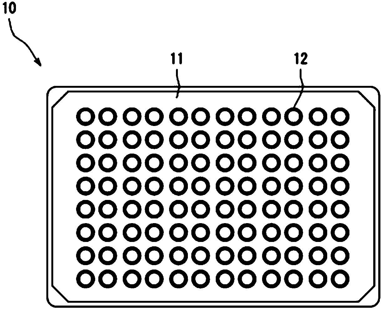
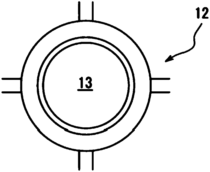
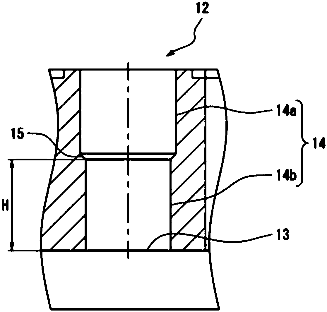
[0058] In this example, an orifice plate of the following specifications made of acrylic resin was used as the orifice plate. It should be noted that, as the holes, holes in which the upper portion of the peripheral wall and the lower portion of the peripheral wall stand approximately perpendicularly to the bottom surface portion were used.

[0059] The inner diameter of the upper part of the surrounding wall: 5.6mm

[0060] Inner diameter of the lower part of the surrounding wall: 5mm

[0061] The inclination angle of the step part: 0 degrees

[0062] Well volume: 250μl

[0063] The volume of the lower part of the surrounding wall: 50.04μl

[0064] The height position of the step part: 2.55mm from the bottom face

[0065] The depth of the hole (the distance from the bottom surface to the opening): 10.8mm

[0066] 100 µl of DMEM (Dulbecco's Modified Eagle's Medium) as a culture solution was dropped into the wells of the aforementioned well plate, and the bottoms of the we...

Embodiment 2

[0068] In this example, as the orifice plate, an orifice plate having the following specifications was used. Except for this, it carried out similarly to Example 1, and photographed the surface of a hole bottom with the inverted microscope. show the result in Figure 7 .

[0069] The inner diameter of the upper part of the surrounding wall: 5.6mm

[0070] Inner diameter of the lower part of the surrounding wall: 5mm

[0071] The inclination angle of the step part: 45 degrees

[0072] Well volume: 250μl

[0073] The volume of the lower part of the surrounding wall: 50.04μl

[0074] The height position of the step part: 2.55mm from the bottom face

[0075] The depth of the hole (the distance from the bottom surface to the opening): 10.8mm


PUM


Abstract

There is provided a well plate including a plate and a well which is opened in an upper surface of the plate, wherein the well includes a flat bottom surface part and a circumferential wall part rising upward from the circumferential edge of the bottom surface part; the circumferential wall part has a stepped part in the circumferential direction at an arbitrary height position; an upper circumferential wall part, which is located above the stepped part in the circumferential wall part, is larger in a cross sectional area than a lower circumferential wall part located below; and the stepped part indicates the lower limit of the liquid level height of a liquid sample contained in the well.

Description

technical field [0001] The present invention relates to an orifice plate and a method of using the same. More specifically, it relates to a method that can improve the reduction in visibility caused by the meniscus effect when observing an orifice plate with a microscope, imaging device, etc., so that even in the hole An orifice plate that can also be observed with sufficient brightness at the periphery of the bottom surface of the invention and a method of use thereof. Background technique [0002] The orifice plate is an experimental instrument or testing instrument composed of plates arranged with multiple recesses (wells or deep wells), and is widely used in biochemical analysis, clinical testing, and the like. Specifically, it is used when injecting a culture solution, a medium, and the like into each well, and observing or measuring cultured cells and the like. In recent years, imaging devices such as CCD (Charge Coupled Device, Charge Coupled Device) cameras are also...

Claims


Application Information

Patent Timeline
Patent Type & Authority Applications(China)
IPC IPC(8): G01N21/03
CPCG01N21/6452B01L2200/14B01L2300/168B01L3/5085B01L2300/0829B01L2300/0851B01L2300/0858B01L2200/12G01N21/01
Inventor 生藤邦夫
Owner DAINIPPON SCREEN MTG CO LTD
Why Eureka
Try Eureka