A self-powered wind direction and wind speed monitor

A technology of wind direction and wind speed and monitoring instrument, which is applied in the direction of fluid velocity measurement, velocity/acceleration/impact measurement, instruments, etc., to achieve the effect of low starting wind speed, good power generation effect and high reliability

Active Publication Date: 2019-10-01
黑龙江中飞利器装备有限公司
View PDF4 Cites 0 Cited by
  • Summary
  • Abstract
  • Description
  • Claims
  • Application Information

AI Technical Summary

Problems solved by technology

However, there are still some key issues that need to be solved urgently in the field of wind direction and wind speed measurement, such as data acquisition, processing and energy supply for continuous remote transmission, low wind speed start-up of the measurement system, etc.

Method used


Image

  • A self-powered wind direction and wind speed monitor
  • A self-powered wind direction and wind speed monitor
  • A self-powered wind direction and wind speed monitor

Examples


Embodiment Construction

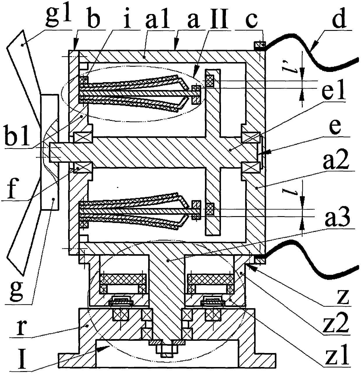
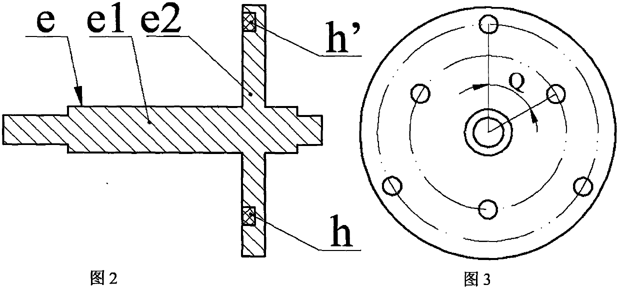
[0015] The end of the side wall a1 of the main body a is installed with an end cover b through screws, the outer side of the bottom wall a2 of the main body a is installed with a flag sail d through the bead c and screws, and the outer side of the side wall a1 of the main body a is provided with a semi-axis a3; the exciter e It is composed of the main shaft e1 and the excitation disc e2. The center of rotation of the excitation disc e2 is the same as that of the main shaft e1; The left end of the main shaft protrudes from the inner cavity of the main body a through the end cover b, and the left end of the main shaft e1 is installed with a flange g with blade g1 through screws; a set of inner magnets h and a set of outer magnets are installed on the excitation plate e2 through screws h', the inner magnet h and the outer magnet h' have the same size and magnetic pole configuration, and are equal in number and are respectively evenly distributed on two circles with different radii...


PUM


Abstract

The invention relates to a self-powered wind direction and wind speed monitor and belongs to the wind power measurement field. A main body is provided with an end cover, flag sails and a semi-shaft; the main shaft of an exciter is mounted on the end cover and the bottom wall of the main body through a bearing; the left end of the main shaft is equipped with blades; the excitation plate of the exciter is provided with inner magnets and outer magnets; the size and number of the inner magnets are identical with the size and number of the outer magnets respectively; the inner magnets and the outermagnets are uniformly distributed at two circumferences with different radiuses; power generating units composed of leaf springs, piezoelectric oscillators, inertia blocks and excited magnets are uniformly arranged on the end cover; the substrates of the piezoelectric oscillators are adjacent to the leaf springs; the folded edges of the substrates abut against the leaf springs; the magnetic polesof the excited magnets, the inner magnets and outer magnets, which have different magnetism, are opposite to each other; before being mounted, the piezoelectric oscillators are of flat and straight structures; after being mounted, the piezoelectric oscillators are of bent structures; the bottom wall of a shell sleeves the semi-shaft; the side wall of the shell is installed on the side wall of themain body; the inner side of the bottom wall of the shell is provided with a circuit board; sensors are uniformly arranged on the outer side the bottom wall of the shell; the semi-shaft is installedon a base through a bearing; two round magnets are embedded in the base; the centers of the round magnets and the centers of the sensors are located on the same circumference; and the round magnets are symmetrically installed at two sides of the semi-shaft.

Description

technical field [0001] The invention belongs to the technical field of wind force measurement, and in particular relates to a self-powered wind direction and wind speed monitor. Background technique [0002] Wind direction and wind speed measurement technology has a wide range of application requirements in meteorology, civil aviation, highways and bridges, and mining industries. At present, new sensors, data acquisition and processing technologies for wind direction and speed measurement have made great progress, among which portable digital wind speed measuring instruments have been widely used in industrial production. However, there are still some key problems that need to be solved urgently in the field of wind direction and wind speed measurement, such as data acquisition, processing and energy supply for continuous remote transmission, low wind speed start-up of the measurement system, and so on. Contents of the invention [0003] The present invention proposes a s...

Claims


Application Information

Patent Timeline
Patent Type & Authority Patents(China)
IPC IPC(8): G01P5/08G01P13/02
Inventor 王淑云钱超平张可
Owner 黑龙江中飞利器装备有限公司
Why Eureka
Try Eureka