
A self-powered wind direction instrument

An anemometer, self-powered technology, applied in the direction of instruments, electrical components, generators/motors, etc., to achieve the effect of low start-up wind speed, good power generation effect, and high reliability

Active Publication Date: 2019-01-29
合肥九州龙腾科技成果转化有限公司
View PDF9 Cites 0 Cited by
  • Summary
  • Abstract
  • Description
  • Claims
  • Application Information

AI Technical Summary

Problems solved by technology

However, there are still some key issues that need to be solved urgently in the field of wind direction and wind speed measurement, such as data acquisition, processing and energy supply for continuous remote transmission, low wind speed start-up of the measurement system, etc.

Method used


Image

  • A self-powered wind direction instrument
  • A self-powered wind direction instrument
  • A self-powered wind direction instrument

Examples


Embodiment Construction

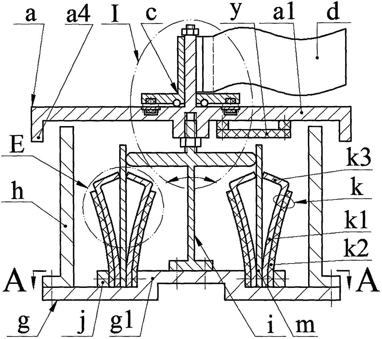
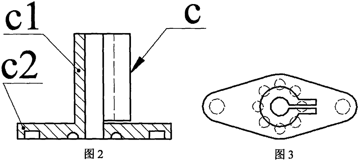
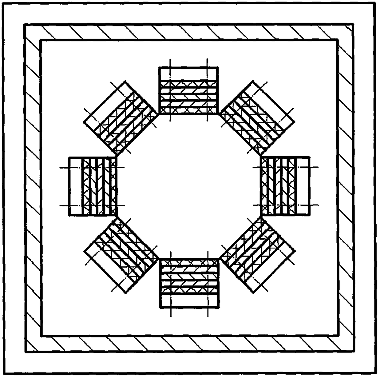
[0015] The top of the plate a1 of the wobble plate a is provided with a semi-axis a2, and a sensor b is installed through a screw. The center of the bottom of the plate a1 is provided with a boss a3 with a threaded hole, and the outer edge is provided with a ring platform a4. The plate a1 The circuit board y is installed on the bottom via screws, and the circuit board y is equipped with an energy conversion circuit, an operation processing circuit and an information transmission system; the sensor b is evenly distributed on the circle centered on the center of the semi-axis a2, and the sensor b is made of nickel with equal thickness The substrate b1 is bonded with the piezoelectric film b2, the ratio of the diameter of the piezoelectric film b2 to the diameter of the deformable part of the nickel substrate b1 is 0.8, and the piezoelectric film b2 is installed facing downwards; the sail frame c is composed of mutually perpendicular sleeves c1 It is composed of the chassis c2, th...


PUM


Abstract

The invention relates to a self-powered anemoscope, belonging to the technical field of wind power measurement. a semi-shaft and sensors are arranged above the swing disc body, a boss, a circular table, and a circuit board are arranged under the disc body, the sensors are uniformly distributed on the circumference by taking the center of the semi-shaft as the circle center, a sail support sleeve with canvas sleeves the semi-shaft, the sail support chassis is pressed on the swing disc body through a group of rollers, two magnets symmetrically arranged at the two sides of the semi-shaft are embedded under the sail support chassis, an outer casing is arranged on a base, an exciter connection board is arranged on the boss of the base, the exciter connection board is provided with a swing rod, an excitation disc is arranged on the swing rod, a stud is arranged on the excitation disc, the stud is connected with the boss of the swing disc, the side wall of the boss of the base is uniformly provided with generating units each consisting of a flat spring and piezoelectric oscillators symmetrically arranged at the two sides of the flat spring, the free end of the flat spring and the edge of the excitation disc contact and don't act with each other, each piezoelectric oscillator is formed by the bonding of a substrate and a piezoelectric sheet, the free end of the substrate is provided with a flange, and the substrate is close to the flat spring and the flange abuts against the flat spring.

Description

technical field [0001] The invention belongs to the technical field of wind force measurement, and in particular relates to a self-powered anemometer. Background technique [0002] Wind direction and wind speed measurement technology has a wide range of application requirements in meteorology, civil aviation, highways and bridges, and mining industries. At present, new sensors, data acquisition and processing technologies for wind direction and speed measurement have made great progress, among which portable digital wind speed measuring instruments have been widely used in industrial production. However, there are still some key problems that need to be solved urgently in the field of wind direction and wind speed measurement, such as data acquisition, processing and energy supply for continuous remote transmission, low wind speed start-up of the measurement system, and so on. Contents of the invention [0003] The present invention proposes a self-powered wind direction ...

Claims


Application Information

Patent Timeline
Patent Type & Authority Patents(China)
IPC IPC(8): H02N2/18G01P5/08G01P13/02
CPCG01P5/08G01P13/02H02N2/185H02N2/186
Inventor 阚君武朱贝贝曾平
Owner 合肥九州龙腾科技成果转化有限公司
Learn More