Large-diameter hole drilling fixing device

A fixing device and large-diameter technology, applied in positioning devices, clamping, supporting, etc., can solve problems such as waste of resources, long initial investment time, complex structure, etc., and achieve simple installation and debugging, compact and novel structure, stable and efficient transmission Effect

Inactive Publication Date: 2018-01-12
迟一
View PDF0 Cites 6 Cited by
  • Summary
  • Abstract
  • Description
  • Claims
  • Application Information

AI Technical Summary

Problems solved by technology

[0002] Drilling equipment is often used in the processing of building materials. The processing of large apertures requires extremely high precision for clamping and fixing. Cannot continue to be used during processing
[0003] In order to solve the above problems, the present invention is proposed, which overcomes the problems of traditional punching and clamping devices, such as difficult installation and debugging due to the complicated structure of stable processing, long investment time in the early stage, waste of manpower and material resources in post-processing, etc., and solves the problems of traditional punching For the clamping device, due to the rigid impact in the clamping process, the workpiece itself is deformed or damaged, and the components in the device are in the rigid impact for a long time, the life is reduced, and the problem is not durable. The traditional punching and clamping device has been improved. The transmission mechanism is simple, resulting in low transmission efficiency and waste of resources for long-term use, so that the present invention has the advantages of compact and novel structure, simple appearance, stable and efficient transmission, simple installation and debugging, etc.

Method used


Image

  • Large-diameter hole drilling fixing device
  • Large-diameter hole drilling fixing device
  • Large-diameter hole drilling fixing device

Examples


Embodiment Construction

[0020] The following will clearly and completely describe the technical solutions in the embodiments of the present invention with reference to the accompanying drawings in the embodiments of the present invention. Obviously, the described embodiments are only some, not all, embodiments of the present invention. Based on the embodiments of the present invention, all other embodiments obtained by persons of ordinary skill in the art without making creative efforts belong to the protection scope of the present invention.

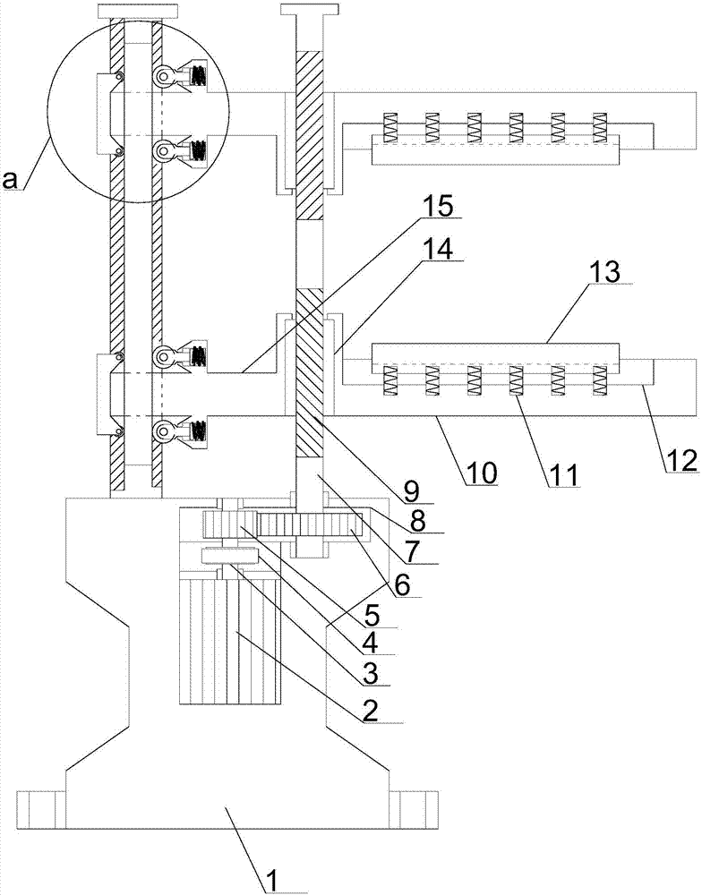
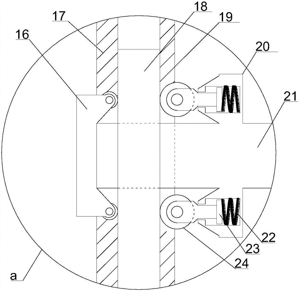
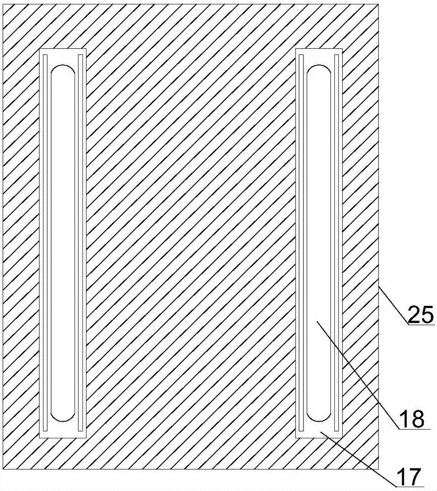
[0021] see Figure 1~6 , in an embodiment of the present invention, a large-diameter drilling fixing device includes a support installation module and a limit sliding clamping module, the support installation module includes an I-shaped support installation column 1, and the I-shaped support installation column 1 The left and right sides of the lower end are symmetrically provided with fixed posts, and the fixed posts are provided with mounting screw holes. Th...


PUM


Abstract

The invention discloses a large-diameter hole drilling fixing device. The large-diameter hole drilling fixing device comprises a supporting mounting module and a limiting sliding clamping module; thesupporting mounting module comprises an I-shaped supporting mounting column; a limiting moving plate is arranged on the left side of the upper end of the I-shaped supporting mounting column; a protective limiting plate is arranged at the upper end of the limiting moving plate; limiting sliding holes are vertically and symmetrically formed in the left side and the right side of the limiting movingplate; the front side and the rear side of each limiting sliding hole are provided with a limiting sliding groove and a limiting moving wheel groove correspondingly by being matched with the limitingmoving plate; the limiting sliding clamping module is arranged on the I-shaped supporting mounting column and comprises a clamping transmission structure which is embedded into the upper half sectionof the interior of the I-shaped supporting mounting column and a double-way clamping structure which is arranged right above the I-shaped supporting mounting column. The large-diameter hole drilling fixing device has the advantages of being compact and novel in structure, concise in appearance, stable and efficient in transmission, easy to mount and debug and the like.

Description

technical field [0001] The invention relates to building material processing equipment, in particular to a large-diameter drilling and fixing device. Background technique [0002] Drilling equipment is often used in the processing of building materials. The processing of large apertures requires extremely high precision for clamping and fixing. Cannot continue to be used in processing. [0003] In order to solve the above problems, the present invention is proposed, which overcomes the problems of traditional punching and clamping devices, such as difficult installation and debugging due to the complicated structure of stable processing, long investment time in the early stage, waste of manpower and material resources in post-processing, etc., and solves the problems of traditional punching For the clamping device, due to the rigid impact in the clamping process, the workpiece itself is deformed or damaged, and the components in the device are in the rigid impact for a long...

Claims


Application Information

Patent Timeline
Patent Type & Authority Applications(China)
IPC IPC(8): B23Q3/06B28D7/04
Inventor 迟一
Owner 迟一
Why Eureka
Try Eureka