Dolly gear driven cantilever crane with balancing counterweight

A technology of gear drive and counterweight, which is applied in the direction of traveling bridge cranes, cranes, load blocks, etc. It can solve the problems of low working level, waste of manpower and material resources, high cost of explosion-proof motors and explosion-proof electric hoists, and achieve convenient operation , The effect of the structure occupying a small space

Inactive Publication Date: 2018-01-12
林霞
View PDF0 Cites 0 Cited by
  • Summary
  • Abstract
  • Description
  • Claims
  • Application Information

AI Technical Summary

Problems solved by technology

[0002] Existing bridge cranes are used in enterprise workshops. The products and raw materials in the workshop need to be transported to the next workshop or other departments in real time; The beam runs back and forth, and the crane can only run back and forth along the cart rails on the cross columns on both sides of the workshop. In this way, the range of goods that the crane hook can lift is within the plane surrounded by the two ends of the two cart rails in the workshop. When the goods on the edge of this plane need to be hoisted, the hook will be pulled obliquely, and the items farther away from this plane (such as outside the workshop door, outside the span) cannot be hoisted. At this time, they can only be transferred by other transportation equipment. , Usually the car drives into the workshop to lift the goods under the hook. If some cars cannot drive in, a track is laid horizontally between the workshop and the next-door workshop, and the special rail car is driven to the hook to deliver the goods, and some are in the workshop. A special cantilever crane is set up a

Method used


Image

  • Dolly gear driven cantilever crane with balancing counterweight
  • Dolly gear driven cantilever crane with balancing counterweight
  • Dolly gear driven cantilever crane with balancing counterweight

Examples


Embodiment approach

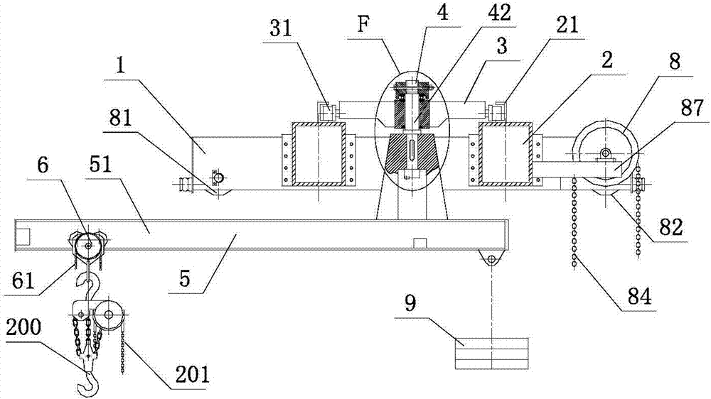
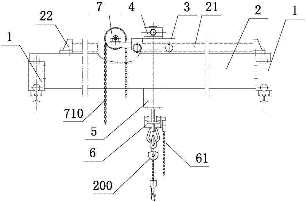
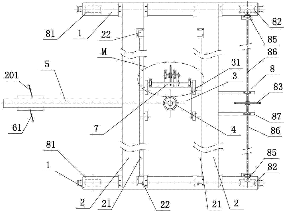
[0026] Such as figure 1 , figure 2 , image 3 As shown, a cantilever crane driven by a counterweight and a trolley gear includes two end girders 1 and two main girders 2, which form a double-girder bridge structure; Cart running device 8; above the two main girders 2, an inverted "U" track 21 is provided; a running trolley 3 is connected between the two rails 21; The running trolley is provided with a gear drive device 7; the running trolley is provided with a rotating mechanism 4; the thrust bearing in the rotating mechanism is connected above the bearing seat and fastened with a lock nut; The lower end of the boom shaft in the rotating mechanism is connected with the cantilever member 5; one end of the cantilever beam 51 on the cantilever member is connected with the hand-pulled sports car 6 with the drive chain 61, and the other end is suspended with a counterweight 9 anti-tipping; The hand-pull chain hoist 200 suspended under the hand-pulled sports car can lift goods; ...


PUM


Abstract

The invention discloses a dolly gear driven cantilever crane with a balancing counterweight. The cantilever crane comprises two end beams and two main beams which form a two-beam crane span structure,wherein a hand-pulled trolley running device is arranged between the two end beams; inverted U-shaped tracks are arranged on the two main beams; a running dolly is arranged between and connected withthe two tracks; the running dolly is provided with a gear drive unit and a rotating mechanism; a thrust bearing on the rotating mechanism is arranged above and connected with a bearing pedestal and fastened via locknuts; the lower end of a suspender shaft in the rotating mechanism is connected with a cantilever member; one end of a cantilever beam on the cantilever member is connected with a hand-pulled trolley and the balancing counterweight is hung on the other side of the cantilever beam for prevention of tilting; a hand-pulled chain hoist is hung below the hand-pulled trolley and capableof hoisting cargos; and the cantilever beam is located below the two main beams and capable of carrying out rotation, and can stretch out of a workshop for operation.

Description

technical field [0001] The present application relates to the field of cranes, in particular to a jib crane with counterweight and trolley gear drive. Background technique [0002] Existing bridge cranes are used in enterprise workshops. The products and raw materials in the workshop need to be transported to the next workshop or other departments in real time; The beam runs back and forth, and the crane can only run back and forth along the cart rails on the cross columns on both sides of the workshop. In this way, the range of goods that the crane hook can lift is within the plane surrounded by the two ends of the two cart rails in the workshop. When the goods on the edge of this plane need to be hoisted, the hook will be pulled obliquely, and the items farther away from this plane (such as outside the workshop door, outside the span) cannot be hoisted. At this time, they can only be transferred by other transportation equipment. , Usually the car drives into the workshop...

Claims


Application Information

Patent Timeline
IPC IPC(8): B66C17/04B66C11/16B66C11/10B66C11/06B66C9/02B66C9/14
Inventor 黄滨林霞
Owner 林霞
Why Eureka
Try Eureka