Water surface automatic tracking and monitoring system for underwater vehicle

A technology of underwater vehicle and monitoring system, which is applied to the control of finding targets, radio wave measurement system, satellite radio beacon positioning system, etc. It can solve problems such as inability to work, limited measurement distance, expensive price, etc., and achieve improved positioning Accuracy, improving accuracy, and ensuring the effect of positioning range

Active Publication Date: 2018-01-12
NORTHWESTERN POLYTECHNICAL UNIV
View PDF12 Cites 25 Cited by
  • Summary
  • Abstract
  • Description
  • Claims
  • Application Information

AI Technical Summary

Problems solved by technology

[0003] Underwater is a complex working environment. When an autonomous underwater vehicle performs underwater operations, its own environmental perception capabilities and external monitoring capabilities are greatly insufficient compared with land and space robots.
Limited by the water body, the electromagnetic wave attenuates quickly in the underwater environment; if the visual sensor is used, the visual image can only be obtained in a short distance, and often cannot work due to the turbidity of the water body; the laser sensor can measure a range of 100m, and The measurement of distance and azimuth is very accurate, but it is expensive and limited by the measurement distance; dead reckoning navigation is based on the change of ship speed to perform integral calculation of position, the error is large, and accumulates with time; therefore, the position measurement of underwater vehicles and communication is best done with underwater acoustic technology

Method used


Image

  • Water surface automatic tracking and monitoring system for underwater vehicle
  • Water surface automatic tracking and monitoring system for underwater vehicle
  • Water surface automatic tracking and monitoring system for underwater vehicle

Examples


Embodiment Construction

[0024] The embodiments of the present invention will be described in detail below, and the examples of the embodiments are exemplary and intended to explain the present invention, but should not be construed as limiting the present invention.

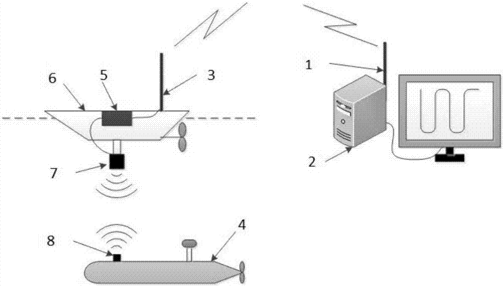
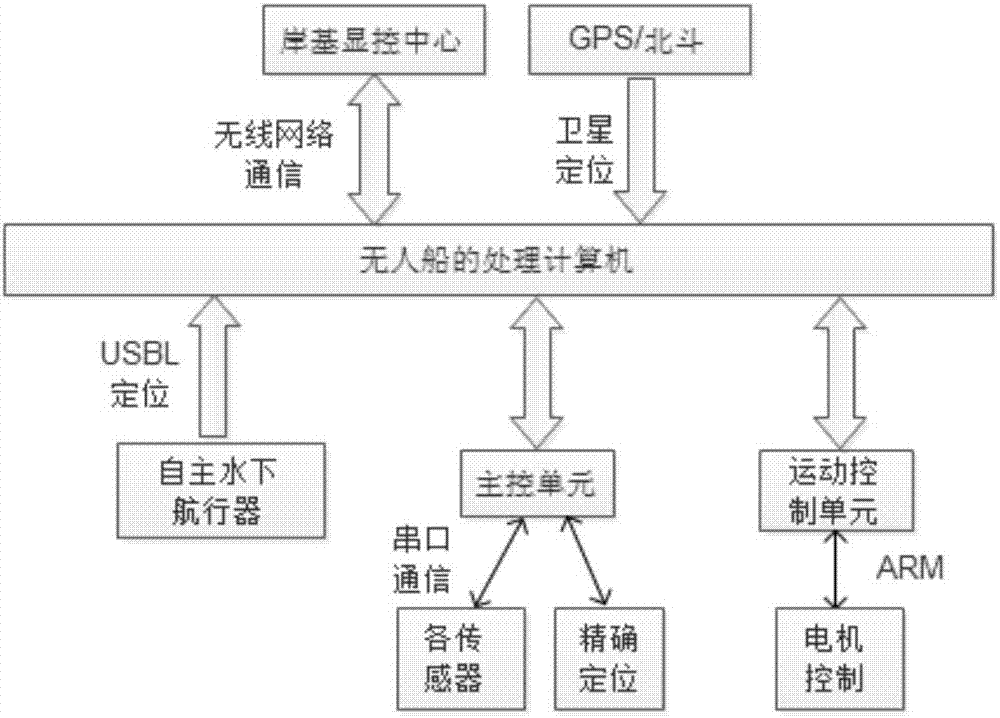
[0025] A water surface automatic tracking and monitoring system for underwater vehicles in this embodiment includes a shore-based display and control center, a wireless network communication system, an unmanned ship tracking platform and an underwater acoustic positioning system.

[0026] The unmanned ship tracking platform uses the underwater acoustic positioning system to obtain the relative position of the underwater vehicle, and combines the position of the unmanned ship tracking platform obtained by the satellite positioning system on the unmanned ship tracking platform to determine the position of the underwater vehicle. And send the unmanned ship tracking platform's own position and the position of the underwater vehicle to the sh...


PUM


Abstract

The invention discloses a water surface automatic tracking and monitoring system for an underwater vehicle. The water surface automatic tracking and monitoring system comprises a shore-based display and control center, a wireless network communication system, an unmanned ship tracking platform and an underwater acoustic positioning system, wherein the shore-based display and control center performs two-way communication with an unmanned ship platform through a wireless network; an unmanned ship obtains a relative position of the autonomous underwater vehicle through the ultra-short base line underwater acoustic positioning system, and the autonomous underwater vehicle is tracked by operating a controller; meanwhile, status information of the underwater vehicle is transmitted to the shore-based display and control center, and further tracking type monitoring of the autonomous underwater vehicle is realized. According to the water surface automatic tracking and monitoring system disclosed by the invention, positioning and tracking control of the unmanned ship to the underwater vehicle are realized by combined use of wireless network communication, the ultra-short base line positioning system and a satellite positioning system, and tracking data are transmitted to workers on a shore, so that high-precision real-time tracking and on-shore remote monitoring of the underwater vehicleare realized.

Description

technical field [0001] The invention relates to the technical field of automatic water surface tracking of underwater vehicles, in particular to an automatic water surface tracking and monitoring system for underwater vehicles. Background technique [0002] As a high-tech tool for ocean development, autonomous underwater vehicles can rely on their own energy to complete various missions assigned to them. They have the characteristics of wide range of activities, small size, light weight, low noise, and good concealment. Both military and civilian fields have broad application prospects. [0003] Underwater is a complex working environment. When an autonomous underwater vehicle performs underwater operations, its own environmental perception capabilities and external monitoring capabilities are greatly insufficient compared with land and space robots. Limited by the water body, the electromagnetic wave attenuates quickly in the underwater environment; if the visual sensor is...

Claims


Application Information

Patent Timeline
Patent Type & Authority Applications(China)
IPC IPC(8): G01C21/16G01S15/02G01S15/50G01S19/45G01S19/47G05D1/12
Inventor 高剑严卫生崔荣鑫王银涛张福斌汤丹妮周斌斌
Owner NORTHWESTERN POLYTECHNICAL UNIV
Why Eureka
Try Eureka