Self-service terminal with water supply function
A self-service terminal and functional technology, applied in the direction of processing coins or valuable banknotes, coin-free or similar appliances, coin-operated equipment for distributing discrete items, etc., can solve the problem that relevant units cannot provide drinking water in time, etc. problems, to achieve the effect of improving service levels
- Summary
- Abstract
- Description
- Claims
- Application Information
AI Technical Summary
Problems solved by technology
Method used
Image

Examples
Embodiment 1
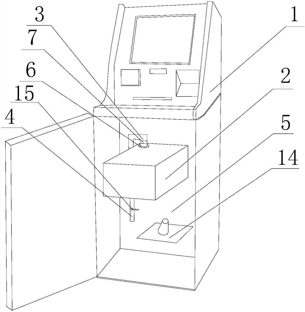
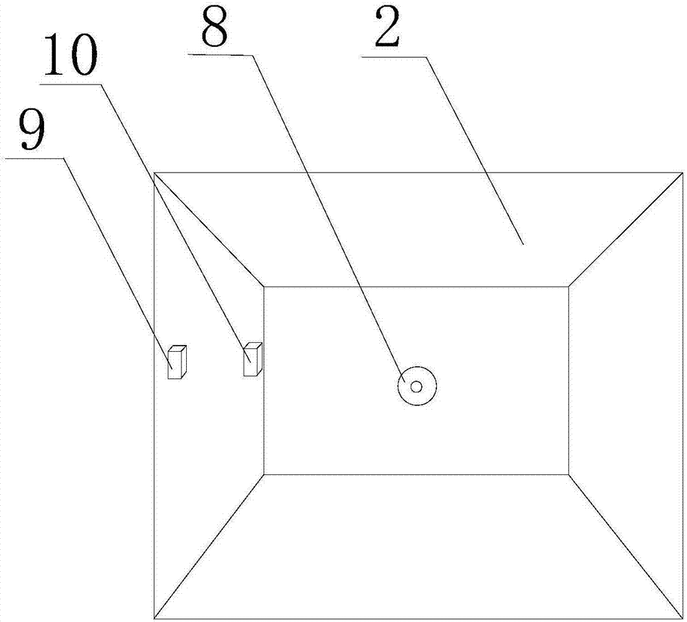
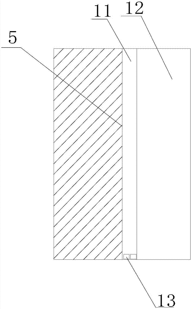
[0026] Such as Figure 1-3 As shown, the self-service terminal with water supply function includes a self-service terminal 1, a water heater 2, a water inlet pipe 3, and a water outlet pipe 4. The lower part of the self-service terminal 1 is provided with an isolation cover 5 and a wiring unit 12. The isolation cover 5 is made of waterproof material, the inside of the isolation cover 5 is provided with a paper cup placement area 14, and a drying chamber 11 is arranged between the wiring unit 12 and the isolation cover 5, and a desiccant 13 is arranged in the drying chamber 11 The water heater 2 is arranged inside the isolation cover 5, the top of the water heater 2 is provided with a water inlet 6, the water inlet 6 is connected to the water inlet pipe 3, and the water inlet port on the water inlet pipe 3 is provided with a water inlet switch 7, and the water inlet switch 7 is for the water flow Switch, the bottom of the water heater 2 is provided with a water outlet 8, the wa...
Embodiment 2
[0028] On the basis of Embodiment 1, the automatic water filling function of the water heater 2 is realized by setting a high water level sensor 9 and a low water level sensor 10 inside the water heater 2. When the low water level sensor 10 monitors the water level information, the water level information is sent to the self-service The processor of the terminal 1, the processor processes the water level information and sends an instruction to control the water inlet switch 7 of the water inlet pipe 3 to open, the water heater 2 to add water, and when the water level reaches a certain position, the high water level sensor 9 is touched, and the high water level sensor 9 transmits the water level information Send to the processor of the self-service terminal 1, the processor processes and issues an instruction to close the water inlet switch 7 of the water inlet pipe 3, and stop adding water.
PUM
 Abstract
Description
Claims
Application Information
PatSnap Eureka turns technology decisions into work you can execute. Powered by our Innovation Knowledge Graph, it runs expert workflows across engineering, life sciences, materials and intellectual property. Get your review-ready output in minutes.


