
Calibration interpolation method under sweeping-frequency mode of signal receiver

An interpolation method and receiver technology, applied in receiver monitoring and other directions, can solve the problems of increased hardware cost, slow speed, and high resource consumption, and achieve the effect of not slow speed and improved response speed

Inactive Publication Date: 2018-01-12
THE 41ST INST OF CHINA ELECTRONICS TECH GRP
View PDF5 Cites 1 Cited by
  • Summary
  • Abstract
  • Description
  • Claims
  • Application Information

AI Technical Summary

Problems solved by technology

[0009] 1. The upper computer software calculates the calibration value: the disadvantage is that the speed is slow and takes a long time
For each frequency sweep, the calibration data must be calculated by the upper computer and then transmitted to the underlying hardware. This kind of data transmission from the upper computer to the underlying hardware will take too long, which will be prominent in occasions where the frequency scanning time is relatively high. its disadvantages;
[0010] 2. The FPGA hardware multiplies and divides the IP core to calculate the calibration value: the disadvantage is that it consumes a lot of resources and increases the hardware cost
In actual engineering, especially when the hardware has been fixed, FPGA resources are limited. Later performance upgrades and maintenance will increase the resource overhead of the FPGA, and there may be insufficient resources. If you replace a new FPGA will inevitably increase the cost

Method used


Image

  • Calibration interpolation method under sweeping-frequency mode of signal receiver
  • Calibration interpolation method under sweeping-frequency mode of signal receiver
  • Calibration interpolation method under sweeping-frequency mode of signal receiver

Examples


Embodiment Construction

[0046]Below in conjunction with accompanying drawing and specific embodiment the present invention is described in further detail:

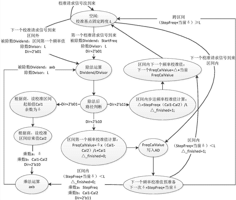
[0047] In the frequency sweeping mode of the signal receiver, the present invention proposes a high-efficiency interpolation method for amplitude calibration, which solves the disadvantages of long computer software calculation time-consuming, hardware IP core resource consumption, etc., making the gap between time and cost To achieve a balanced high efficiency, the overall technical solution such as image 3 shown.

[0048] The detailed process of FPGA linear interpolation calibration method status is explained step by step:

[0049] Step 1: The original calibration data is written into the RAM of the underlying FPGA when the machine is turned on, as part of the initialization of the whole machine parameters;

[0050] Step 2: When the frequency sweep function is called, each frequency point needs to be written in the matching calibration data,...


PUM


Abstract

The invention discloses a calibration interpolation method under a sweeping-frequency mode of a signal receiver, and belongs to the technical field of microwave tests. In the method provided by the invention, data transmission is performed only once during startup initialization, in subsequent each sweeping-frequency process, interpolation calibration is implemented by hardware, and thus a response speed is greatly improved so as to be enough to deal with fast sweeping-frequency occasions. The method needs less resource consumption, and has extremely strong engineering practicability, so as toavoid the awkward situation that hardware IP core resources are insufficient to use; the method gives consideration to both speed and resource quantity, so that the speed is not slow and the resourcequantity is not large, and thus the method is an efficient balance scheme.

Description

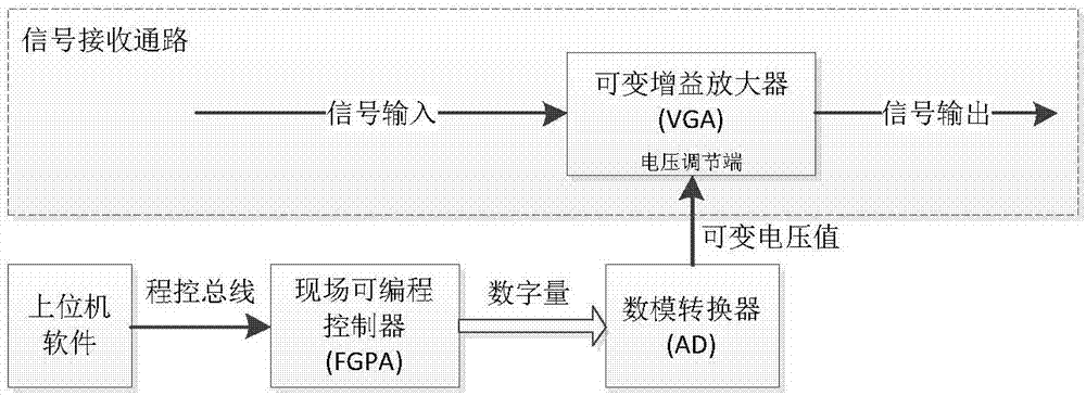
technical field [0001] The invention belongs to the technical field of microwave testing, and in particular relates to a calibration interpolation method in a frequency sweep mode of a signal receiver. Background technique [0002] Since the signal receiver has different frequency response characteristics in the whole wide frequency band, the amplitude calibration must be performed for each frequency point. The hardware circuit implementation of the amplitude calibration is as follows: figure 1 shown. The amplitude adjustment can be realized by changing the voltage of the voltage adjustment terminal of the variable gain amplifier (VGA), and this amplitude adjustment is usually linear, that is, the input voltage value and the gain value have a linear relationship; the digital quantities acting on AD are all It must be communicated to the AD chip in strict accordance with the inherent timing of the AD chip, and this timing control is generated by the FPGA. The calculation me...

Claims


Application Information

Patent Timeline
Patent Type & Authority Applications(China)
IPC IPC(8): H04B17/21
Inventor 刘忠林丁志钊白亮王磊于淼
Owner THE 41ST INST OF CHINA ELECTRONICS TECH GRP
Learn More