Converter arrangement and method for short-circuit protection thereof

A technology of converters and branches, applied in the direction of output power conversion devices, circuit devices, emergency protection circuit devices, etc., can solve problems such as short-circuit current decline, and achieve the effect of improving protection

Inactive Publication Date: 2018-01-12
SIEMENS AG
View PDF4 Cites 2 Cited by
  • Summary
  • Abstract
  • Description
  • Claims
  • Application Information

AI Technical Summary

Problems solved by technology

Then the short circuit current still flowing in the DC voltage line due to the inductance of the wire decays completely

Method used


Image

  • Converter arrangement and method for short-circuit protection thereof
  • Converter arrangement and method for short-circuit protection thereof
  • Converter arrangement and method for short-circuit protection thereof

Examples


Embodiment Construction

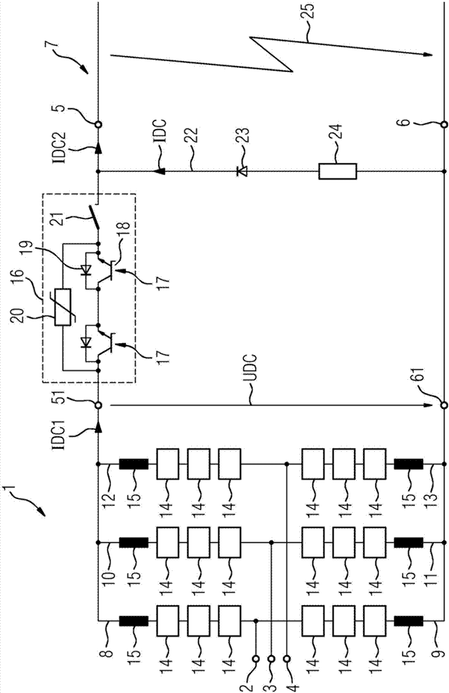
[0032] figure 1An embodiment of the converter arrangement 1 according to the invention is shown in detail. The converter device 1 comprises three AC voltage connections 2 , 3 and 4 which are designed to connect the converter device 1 to a three-phase AC network. Furthermore, the converter device 1 comprises a first direct voltage connection 5 and a second direct voltage connection 6 for connection to a direct voltage line 7 . Accordingly, in the present exemplary embodiment, the converter device 1 is designed as three-phase, wherein the invention is of course not limited to a three-phase embodiment. It comprises a first phase branch 8 extending between a first direct voltage pole 51 and a first alternating voltage connection 2 , a second phase module branch extending between the first alternating voltage connection 2 and a second direct voltage pole 61 9, a third phase module branch 10 extending between the first DC voltage pole 51 and the second AC voltage connection 3, a ...


PUM


Abstract

The invention relates to a converter arrangement (1) comprising a first phase module branch (8) having a first series connection of bipolar sub-modules (14), each comprising at least one energy storeand at least one power semiconductor switch, wherein the first phase module branch extends between a first alternating voltage connection (2) and a first direct voltage pole (51), a second phase module branch (9) having a second series connection of the bipolar sub-modules, which extends between the first alternating voltage connection and a second direct voltage pole (61), a third phase module branch (10) having a third series connection of the bipolar sub-modules, which extends between a second alternating voltage connection and the first direct voltage pole, and a fourth phase module branch(11) having a fourth series connection of the bipolar sub-modules, which extends between the second alternating voltage connection and the second direct voltage pole, wherein each sub-module can be bridged, independently of the current direction, by means of a bridging unit (33) arranged parallel to the connection terminals thereof, and wherein the first direct voltage pole (51) is connected to afirst direct voltage connection (5) and the second direct voltage pole (61) is connected to a second direct voltage connection (6). The invention is characterized by a direct voltage switch (16), which is arranged between one of the direct voltage poles and the associated direct voltage connection, and a freewheeling path (22) which extends between the two direct voltage connections and comprisesa semiconductor element having a blocking and a bypass direction. The invention further relates to a method for short-circuit protection of the converter arrangement (1).

Description

technical field [0001] The invention relates to a converter arrangement comprising a first phase module branch with a first series circuit of bipolar submodules, the submodules each comprising at least one energy store and at least one power semiconductor switching unit, wherein the first phase A module branch extends between the first AC voltage connection and the first DC voltage pole; a second phase module branch with a second series circuit of bipolar submodules, wherein the second phase module branch is at the first AC voltage Extending between the connection and the second DC voltage pole; a third phase module branch of a third series circuit with bipolar submodules, wherein the third phase module branch is between the second AC voltage connection and the first DC voltage pole and a fourth phase module branch of a fourth series circuit with bipolar submodules, wherein the fourth phase module branch extends between the second AC voltage connection and the second DC voltag...

Claims


Application Information

Patent Timeline
Patent Type & Authority Applications(China)
IPC IPC(8): H02H9/02H02M7/483H02H7/122
CPCH02H7/1222H02M7/483H02H9/02H02M7/4835H02M1/32H02H7/122H02M7/49H02M5/4585
Inventor 蒋旭M-M.巴克兰A.舍恩
Owner SIEMENS AG
Why Eureka
Try Eureka