
Multi-rotor unmanned aerial vehicle dynamic experimental device and experimental method

A multi-rotor unmanned and experimental device technology, applied in the field of unmanned aerial vehicles, can solve the problems of only testing and other problems, and achieve the effect of improving test accuracy, multiple test functions, and high test accuracy

Inactive Publication Date: 2018-01-16
NORTHWESTERN POLYTECHNICAL UNIV
View PDF8 Cites 12 Cited by
  • Summary
  • Abstract
  • Description
  • Claims
  • Application Information

AI Technical Summary

Problems solved by technology

[0007] In order to overcome the deficiency in the prior art that only a single type and a single wheelbase power system parameter can be tested, the present invention proposes a multi-rotor unmanned aerial vehicle power test device and test method

Method used


Image

  • Multi-rotor unmanned aerial vehicle dynamic experimental device and experimental method
  • Multi-rotor unmanned aerial vehicle dynamic experimental device and experimental method
  • Multi-rotor unmanned aerial vehicle dynamic experimental device and experimental method

Examples


Embodiment Construction

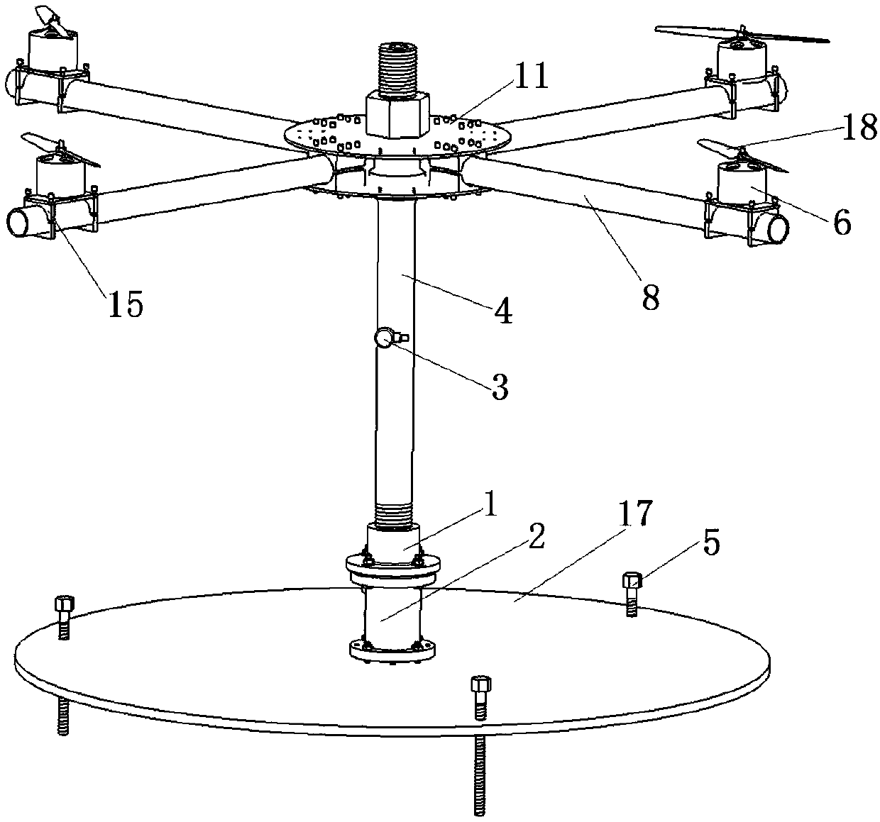
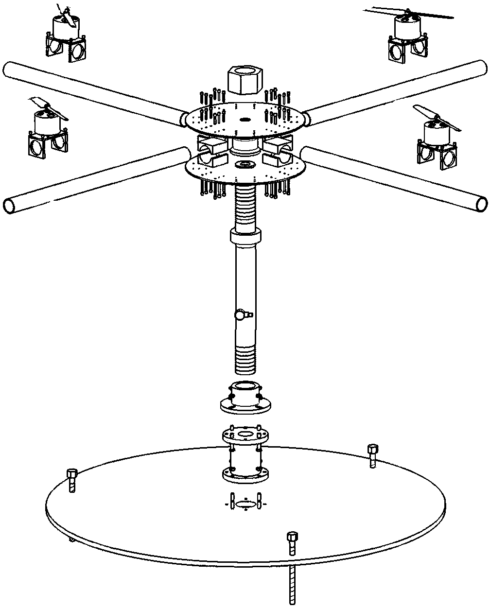
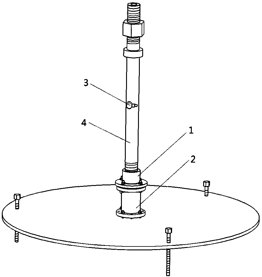
[0048] The present embodiment is a multi-rotor unmanned aerial vehicle power experiment device including a chassis 17, a support rod 4, a sensor seat 1, a tension sensor 2, a vibration sensor 3 and a rotorcraft simulation platform.

[0049] Wherein, the tension sensor 2 is fixed on the center of the upper surface of the chassis 17 by bolts; the sensor seat 1 is located at the upper end of the tension sensor, and is fixed on the upper surface of the upper flange of the tension sensor. The lower end of the support rod 4 is installed in the central hole of the sensor base 1 through threads. The center plate 11 of the rotorcraft simulation platform is mounted on the upper end of the support rod 4 by threads, and is fastened by nuts 9; 2 to 4 pairs of arms 8 are evenly distributed and fixed on the circumferential surface of the center plate. A movable motor base 15 is installed at the cantilever end of each said machine arm; each tested motor 6 is fixed on the upper surface of each...


PUM


Abstract

Disclosed are a multi-rotor unmanned aerial vehicle dynamic experimental device and an experimental method. An experimental platform can be built on the basis of a rotor aircraft model comprising an airframe, arms and motors, and the power, current, voltage, total tension and vibration acceleration of power sources, electronic speed controllers, motors and propellers of dynamic systems of different rotor aircrafts with different axes can be detected. According to the invention, by arranging the structure reasonably, a power system is arranged as high as possible, the reliability of the structure during an experiment is guaranteed and the tension is accurately transmitted; and the influence of the ground effect on the airflow of propellers is decreased, and the interference of experimentalplatform equipment and the ground effect to the operating conditions of the propellers is also decreased. The experimental method can test the dynamic parameters of four-axis rotor aircrafts, six-axisrotor aircrafts and eight-axis rotor aircrafts, and qualitatively measure the parameters of the rotor aircrafts with different axle bases and different axes by changing the axle bases, has the characteristics of complete test functions and high test accuracy, has great practical significances for optimizing the overall layout of the rotor aircrafts and improving the performance of the rotor aircrafts, and also has great market potentials.

Description

technical field [0001] The invention relates to the technical field of unmanned aerial vehicle, in particular to a dynamic experiment device and testing method of an unmanned aerial vehicle rotorcraft system. Background technique [0002] At present, the drone market is mainly divided into fixed-wing and rotary-wing aircraft. Because of the advantages of vertical take-off and landing, convenient maintenance, and easy-to-use, the rotorcraft is widely used in the market and has been greatly developed. Aerial cameras as small as a few kilograms and special machines as large as hundreds of kilograms have been widely used in the industrial field. [0003] At present, there are many different types of rotorcraft designed by different UAV manufacturers, and the design process is already mature, but in fact, this "mature design" often comes from experience, and the overall design of the rotorcraft is not precise. and parameterization. This refined design depends on the parameters ...

Claims


Application Information

Patent Timeline
Patent Type & Authority Applications(China)
IPC IPC(8): B64F5/60
Inventor 安伟刚折智强宋笔锋王海峰
Owner NORTHWESTERN POLYTECHNICAL UNIV
Learn More