Detection equipment and detection method for torque spanners

A technology of testing equipment and wrench, which is applied in the testing of mechanical components, testing of machine/structural components, and measurement of torque/torsion force during tightening. It can solve the problems of high sampling frequency, inaccurate torque detection value, and accuracy of torque indication. Low-level problems, achieve high measurement accuracy, improve replacement efficiency, and improve adaptability

Pending Publication Date: 2018-01-16
中国测试技术研究院力学研究所
View PDF7 Cites 4 Cited by
  • Summary
  • Abstract
  • Description
  • Claims
  • Application Information

AI Technical Summary

Problems solved by technology

[0006] The purpose of the present invention is to overcome the problem that in the existing torque wrench detection device, the sensor is fixedly installed with the fixed stand, so that the sensor cannot rotate together with the torque wrench, and the accuracy of the torque indication is low. The impact mode of the sensor will cause the torque to attenuate, resulting in the technical problem of inaccurate torque detection value. A torque wrench detection device and its detection method are provided. The detection device uses a dynamic torque sensor, and the rotating shaft of the dynamic torque sensor rotates with the torque wrench , will not impact the torque sensor, can simulate the actual state of the bolt tightening, dynamically detect the torque during the bolt tightening process, and can be used for the verification, calibration and testing of electric and pneumatic torque wrenches; and the sampling frequency is very high , can collect the instantaneous peak output of the tested torque wrench to ensure higher measurement accuracy

Method used


Image

  • Detection equipment and detection method for torque spanners
  • Detection equipment and detection method for torque spanners
  • Detection equipment and detection method for torque spanners

Examples


Embodiment 1

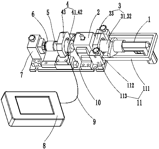
[0040] Such as Figure 1 to Figure 4 As shown, the detection equipment of the torque wrench of the present embodiment includes a frame, a dynamic torque sensor 2 and a bolt clamping part 6, one end of the rotating shaft 21 of the dynamic torque sensor 2 is used for installing the torque wrench 1, and the other end is connected with the bolt clamp The frame is provided with a positioning bracket for installing the dynamic torque sensor 2, and the shell of the dynamic torque sensor 2 is supported on the positioning bracket so that the rotating shaft 21 of the dynamic torque sensor can rotate with the torque wrench 1.

[0041] The detection equipment of this embodiment adopts a dynamic torque sensor, and the detected torque wrench is directly connected with the sensor shaft, and the shaft of the dynamic torque sensor rotates with the torque wrench, which will not impact the torque sensor, and can simulate the actual state when the bolt is tightened. The torque during the bolt tig...

Embodiment 2

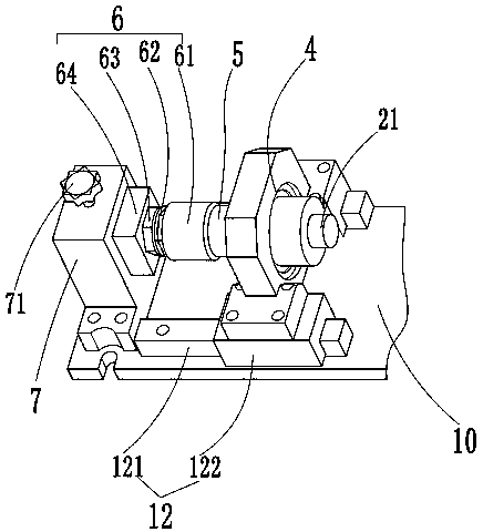
[0043] Such as Figure 1 to Figure 4 As shown, according to the detection device of the torque wrench described in Embodiment 1, the bolt clamping part 6 of the present embodiment is provided with a clamping structure for installing a test nut 62 and a test bolt 63, and is also provided with a device for limiting the movement direction of the bolt and nut assembly. The limiting structure is used to eliminate the interference of the relative movement of the test bolt and the test nut, and the clamping structure is provided with an adjustable clamping part for adjusting the clamping size. The bolt clamping part is used to install the test nut and the test bolt, and the limit structure is used to eliminate the interference of the relative movement of the test bolt and the test nut, restrict the axial and radial degrees of freedom of the test bolt, and only be able to rotate axially, restricting the test The axial and radial degrees of the nut are automatic and cannot be rotated, ...

Embodiment 3

[0047] Such as Figure 1 to Figure 4 As shown, according to the detection device of the torque wrench described in embodiment 1 or embodiment 2, in this embodiment, such as figure 2 As shown, a stop bolt 71 is also provided on the fixed support 7, and a threaded hole for installing the stop bolt 71 is provided on the fixed support 7, and the threaded hole communicates with the nut sleeve 64, and the stop bolt 71 Realize the stopping operation of the bolt and nut assembly.

[0048] Further, the sensor rear end bearing seat 43 is connected with a sliding guide rail part 12, including a guide rail slider 122 and a guide rail 121, and the sensor rear end bearing seat 43 is installed on the guide rail slider 122, and the guide rail 121 The extension direction is the same as the dynamic torque sensor 2 axial direction. The bearing seat at the rear end of the sensor slides on the guide rail through the slider of the guide rail, which is used to adjust the position of the bearing s...


PUM


Abstract

The invention discloses a detection technology for torque spanners. Detection equipment for the torque spanners comprises a rack, a dynamic torque sensor and a bolt clamping part, wherein one end of arotary shaft of the dynamic torque sensor is used for installing the torque spanner, and the other end of the rotary shaft of the dynamic torque sensor is connected with the bolt clamping part; the rack is provided with a positioning bracket for installing the dynamic torque sensor; a shell of the dynamic torque sensor is arranged on the positioning bracket in a supporting manner, so that a rotary shaft of the dynamic torque sensor can rotate along the torque spanners. According to the detection equipment disclosed by the invention, the dynamic torque sensor is adopted, the rotary shaft of the dynamic torque sensor rotates along the torque spanners, so that no impact is caused to the torque sensor, the actual state when a bolt is screwed can be simulated, the torque in the screwing process of the bolt can be dynamically detected, and the detection equipment can be used for verification, calibration and test of electric and pneumatic torque spanners; the sampling frequency is very high; an instantaneous peak value output by the detected torque spanners can be acquired, so that higher measurement accuracy can be guaranteed.

Description

technical field [0001] The invention relates to the field of torque wrench detection, in particular to a torque wrench detection device and a detection method thereof. Background technique [0002] Torque wrenches are widely used in automobile manufacturing, equipment manufacturing, transportation and other industries. With the development of the industrial level, the control of the assembly process is becoming more and more strict. The tightening of bolts and nuts is an important part of the control of the assembly process of industrial products. Therefore, the performance of the torque wrench is getting more and more attention, especially the electric and The pneumatic torque wrench is driven by electricity and gas pressure, and can directly affect the quality of assembly through the precise control of its output torque, which is of great significance for reducing the occurrence of traffic accidents and reducing the safety hazards of public works. [0003] The torque wren...

Claims


Application Information

Patent Timeline
Patent Type & Authority Applications(China)
IPC IPC(8): G01L5/24G01M13/00
Inventor 易伟李程王楠陈世超
Owner 中国测试技术研究院力学研究所
Why Eureka
Try Eureka