Device and method for measuring pressure field generated by fishtailing of bionic fish

A technology of measuring device and measuring method, which is applied in the direction of fluid pressure measurement using optical methods, and can solve problems such as relatively few researches on pressure fields.

Pending Publication Date: 2018-01-16
CHINA THREE GORGES UNIV
View PDF4 Cites 5 Cited by
  • Summary
  • Abstract
  • Description
  • Claims
  • Application Information

AI Technical Summary

Benefits of technology

This technology allows us to accurately capture how well an animal moves through water without being affected or damaged from its movements. By setting certain parameters on each part inside our device, we get detailed knowledge about what makes it work better than other methods like tube measurements alone.

Problems solved by technology

This patented technical problem addressed in this patents relates to studying the movement of living fish during their natural motion without being affected by external forces like waves caused by currents that affect them. Current techniques involve either physical observation with probing tools or numerical simulations involving particle imagery measurements which may lack accuracy due to factors like contact between the fish' s head and tails. To overcome these issues, new ways were developed called pneumatic fluorescence technique (PFT). By capturing the velocity fields through certain types of particles, we found that they could accurately represent realistically moving fish motions.

Method used


Image

  • Device and method for measuring pressure field generated by fishtailing of bionic fish
  • Device and method for measuring pressure field generated by fishtailing of bionic fish
  • Device and method for measuring pressure field generated by fishtailing of bionic fish

Examples


Embodiment Construction

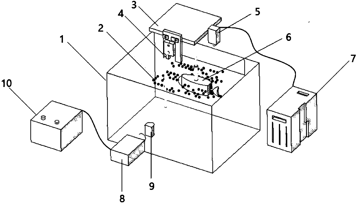
[0025] Such as figure 1 As shown, a pressure field measurement device for bionic fish tail swinging includes a transparent glass fiber reinforced plastic tank 1, a high-energy laser 8, and a D-shaped cylindrical lens 9.

[0026] PIV tracer particles 2 are evenly distributed inside the transparent glass fiber reinforced plastic water tank 1, and when the tail of the mechanical bionic fish 6 swings, it drives the PIV tracer particles 2 in the water tank to move, resulting in displacement;

[0027] The operating frame 3 is fixed directly above the transparent glass fiber reinforced plastic tank 1, and the center of the operating frame 3 is connected to the dorsal fin of the mechanical bionic fish 6 through a retractable mechanical arm. Since the mechanical arm can be stretched, the height of the mechanical bionic fish 6 in the water body can be adjusted . The front view direction of the operating frame 3 is provided with a miniature pressure sensor 4, and its pressure sensing el...


PUM

PropertyMeasurementUnit
Particle sizeaaaaaaaaaa

Abstract

The invention relates to a device and method for measuring the pressure field generated by fishtailing of bionic fish. The device comprises a transparent glass fiber reinforced plastic water tank, a high-energy laser and a D-type cylindrical lens, and is characterized in that PIV (Particle Image Velocimetry) tracking particles are uniformly distributed inside the transparent glass fiber reinforcedplastic water tank, the PIV tracking particles in the water tank are driven to move when the tail of the mechanical bionic fish swings so as to generate displacement; an operating frame is fixed in the transparent glass fiber reinforcement plastic water tank, the operating frame is connected with a dorsal fin of the mechanical bionic fish through an extensible mechanical arm, the operating frameis provided with a miniature pressure sensor, one side of the operating frame is provided with a CCD camera, and the CCD camera is connected with a post-processing system; a point light source generated by the high-energy laser penetrates through a flat-plane side of the D-type cylindrical lens and generates an area light source through refraction of a curved-surface side of the D-type cylindricallens, the area light source penetrates through the transparent glass fiber reinforced plastic water tank and irradiates on a plane where a center line of the mechanical bionic fish is located, and the PIV tracking particles of the plane is lightened and thus be captured by the CCD camera. The pressure field can be acquired from velocity field data of the PIV, the instantaneous pressure of a pointis monitored in real time through the miniature pressure sensor so as to serve as a reference pressure point for solving a volume control method, and thus the pressure field generated by fishtailingof the fish body can be accurately acquired.

Description


Claims


Application Information

Patent Timeline
Owner CHINA THREE GORGES UNIV
Why Eureka
Try Eureka