
An array forward-looking SAR imaging method

An imaging method and array synthesis technology, applied in the field of array forward-looking SAR imaging, can solve the problems of imaging performance degradation and achieve the effect of equal resolution and low dependence on real aperture

Active Publication Date: 2022-03-29
XIDIAN UNIV +1
View PDF6 Cites 0 Cited by
  • Summary
  • Abstract
  • Description
  • Claims
  • Application Information

AI Technical Summary

Problems solved by technology

Imaging performance is limited by the principle of single-pulse angle measurement. In complex low-contrast scenes, imaging performance degrades rapidly

Method used


Image

  • An array forward-looking SAR imaging method
  • An array forward-looking SAR imaging method
  • An array forward-looking SAR imaging method

Examples


Embodiment Construction

[0057] The following will clearly and completely describe the technical solutions in the embodiments of the present invention with reference to the accompanying drawings in the embodiments of the present invention. Obviously, the described embodiments are only some, not all, embodiments of the present invention. Based on the embodiments of the present invention, all other embodiments obtained by persons of ordinary skill in the art without making creative efforts belong to the protection scope of the present invention.

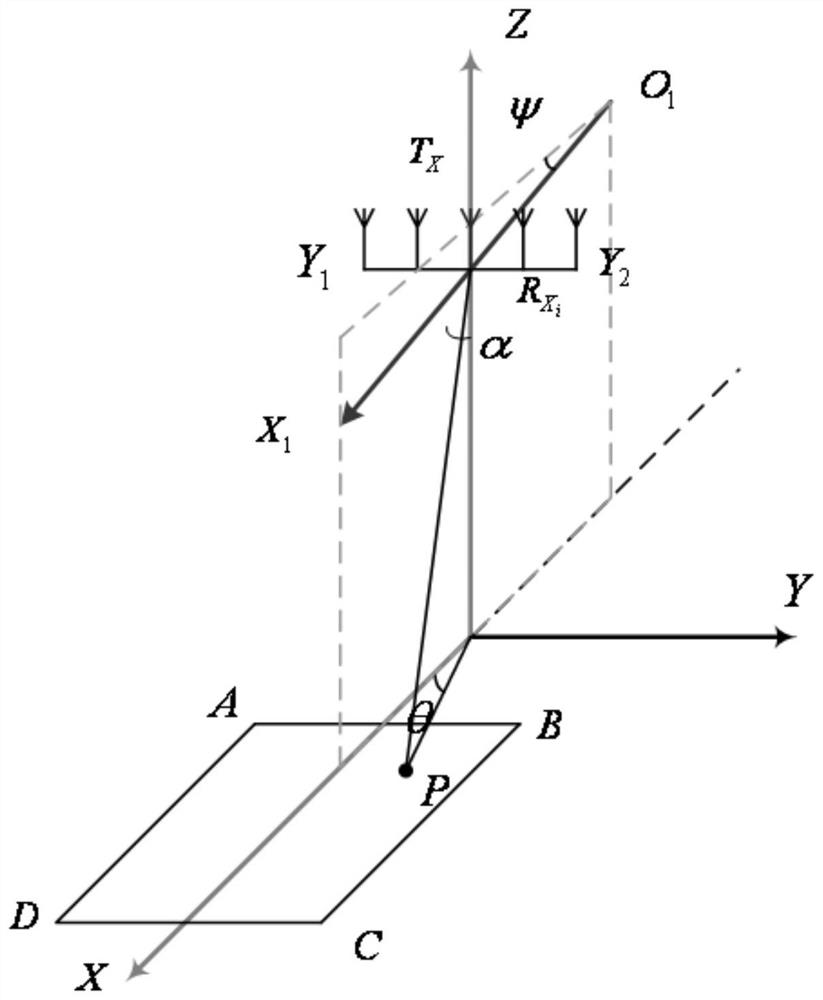
[0058] An embodiment of the present invention provides an array forward-looking SAR imaging method, the system geometric model is as follows figure 1 As shown, the projection of the radar track direction on the ground is the X axis, the distribution direction of the antenna array is the Y axis, and the height above the ground is the Z axis, and a rectangular coordinate system is established.

[0059] o 1 x 1 is the track, the angle between the track and the ...


PUM


Abstract

The invention belongs to the field of radar technology, and discloses an array forward-looking SAR imaging method. On the basis of traditional real-aperture imaging and synthetic aperture imaging, combined with synthetic aperture and real aperture, they work together to realize high resolution of the direction of the forward-looking area. ; By transmitting a large bandwidth signal and range pulse compression to obtain high resolution in the range direction, aiming at the Doppler ambiguity problem in forward-looking imaging, the Doppler ambiguity is solved by multi-channel adaptive zero-point constrained beamforming to obtain the final imaging As a result, high-resolution imaging of the forward-looking scene is possible.

Description

technical field [0001] The invention belongs to the technical field of radar, and in particular relates to an array forward-looking SAR imaging method, which can be used for high-resolution imaging of forward-looking scenes. Background technique [0002] In application fields such as precision guidance and battlefield reconnaissance, there is an urgent need for high-resolution imaging of the front area, that is, forward-looking imaging. In the forward-looking imaging mode, the flight direction of the platform is close to the same as the range direction, and the azimuth direction is defined as the vertical flight direction. Not only is it difficult to distinguish the azimuth due to the limited Doppler diversity in the forward-looking area, but also the symmetrical scenes on both sides of the motion course will have the same Doppler, which causes left and right blur in azimuth, leads to the problem of strong coupling in range and azimuth and Doppler ambiguity in forward-lookin...

Claims


Application Information

Patent Timeline
Patent Type & Authority Patents(China)
IPC IPC(8): G01S13/90
Inventor 张磊卢景月张曼万欣
Owner XIDIAN UNIV
Learn More