

Anti-pressure high protection watch
A high-protection, watch technology, applied in the field of watches, can solve the problems of weak watch protection, unclean wiping, inconvenient watch maintenance, etc., and achieve the effect of convenient maintenance and strong protection
- Summary
- Abstract
- Description
- Claims
- Application Information
AI Technical Summary
Problems solved by technology
Method used
Image

Examples
Embodiment 1
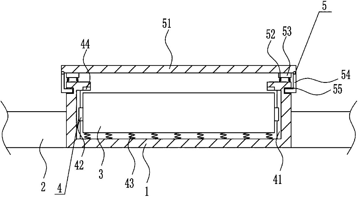
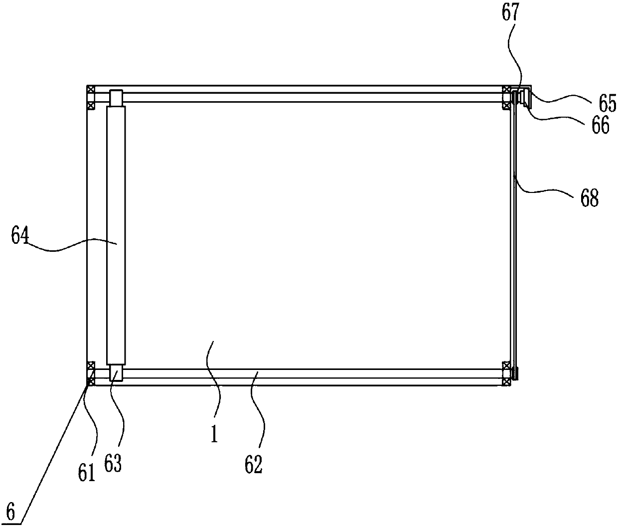
[0035] A pressure-resistant high-protection watch, such as Figure 1-6 As shown, it includes a cavity 1, a watch strap 2, a dial 3, a buffer mechanism 4 and a protective mechanism 5. A strap 2 is provided on the left and right sides of the cavity 1, a dial 3 is provided in the middle of the cavity 1, and a cavity 1 is provided. A buffer mechanism 4 is provided on the inner wall, and a protective mechanism 5 is provided on the top of the cavity 1 .
Embodiment 2
[0037] A pressure-resistant high-protection watch, such as Figure 1-6 As shown, it includes a cavity 1, a watch strap 2, a dial 3, a buffer mechanism 4 and a protective mechanism 5. A strap 2 is provided on the left and right sides of the cavity 1, a dial 3 is provided in the middle of the cavity 1, and a cavity 1 is provided. A buffer mechanism 4 is provided on the inner wall, and a protective mechanism 5 is provided on the top of the cavity 1 .
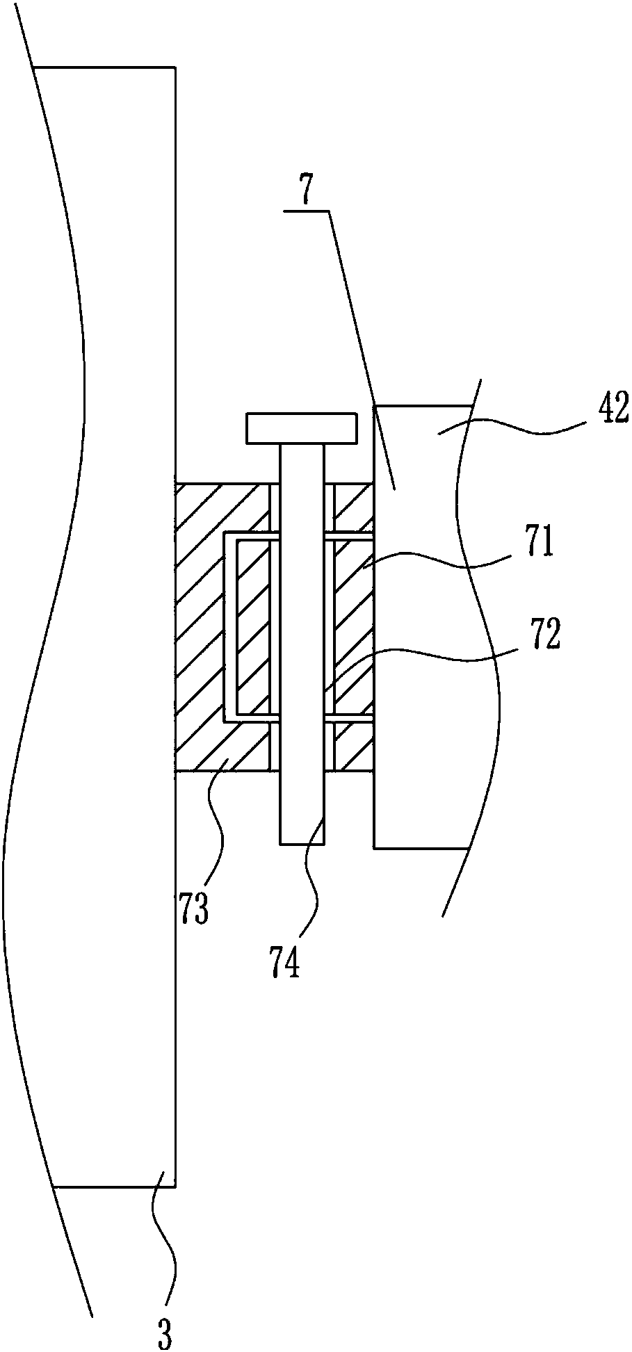
[0038] The buffer mechanism 4 includes a slide rail 41, a slide block 42, a first spring 43 and a rubber pad 44. The left and right sides of the cavity 1 are symmetrically provided with a slide rail 41, and the slide rail 41 is slidably provided with a slide block 42. The dial 3 The middle parts of the left and right sides are connected with the two left and right sliders 42 , and rubber pads 44 are symmetrically arranged on the left and right sides of the top of the cavity 1 , and the rubber pads 44 are located above the left and ...
Embodiment 3
[0040] A pressure-resistant high-protection watch, such as Figure 1-6 As shown, it includes a cavity 1, a watch strap 2, a dial 3, a buffer mechanism 4 and a protective mechanism 5. A strap 2 is provided on the left and right sides of the cavity 1, a dial 3 is provided in the middle of the cavity 1, and a cavity 1 is provided. A buffer mechanism 4 is provided on the inner wall, and a protective mechanism 5 is provided on the top of the cavity 1 .
[0041] The buffer mechanism 4 includes a slide rail 41, a slide block 42, a first spring 43 and a rubber pad 44. The left and right sides of the cavity 1 are symmetrically provided with a slide rail 41, and the slide rail 41 is slidably provided with a slide block 42. The dial 3 The middle parts of the left and right sides are connected with the two left and right sliders 42 , and rubber pads 44 are symmetrically arranged on the left and right sides of the top of the cavity 1 , and the rubber pads 44 are located above the left and ...
PUM
 Abstract
Description
Claims
Application Information