Eureka AIR delivers breakthrough ideas for toughest innovation challenges, trusted by R&D personnel around the world.

Rotor two-gang pressure shaft assembly line

A technology for assembling production lines and rotors, which is applied in the manufacture of stator/rotor bodies, etc., can solve problems such as low efficiency, and achieve the effects of high production efficiency, prevention of crush injury and low production cost

Inactive Publication Date: 2018-01-16
刘国银
View PDF6 Cites 0 Cited by
  • Summary
  • Abstract
  • Description
  • Claims
  • Application Information

AI Technical Summary

Problems solved by technology

[0002] The rotor is the key part of the motor. The rotor is composed of parts such as the rotating shaft and the iron core. In the assembly process of the rotor, the rotating shaft needs to be pressed into the iron core respectively. The pressing of the rotating shaft in the prior art is done manually. way inefficient

Method used


Image

  • Rotor two-gang pressure shaft assembly line

Examples


Embodiment Construction

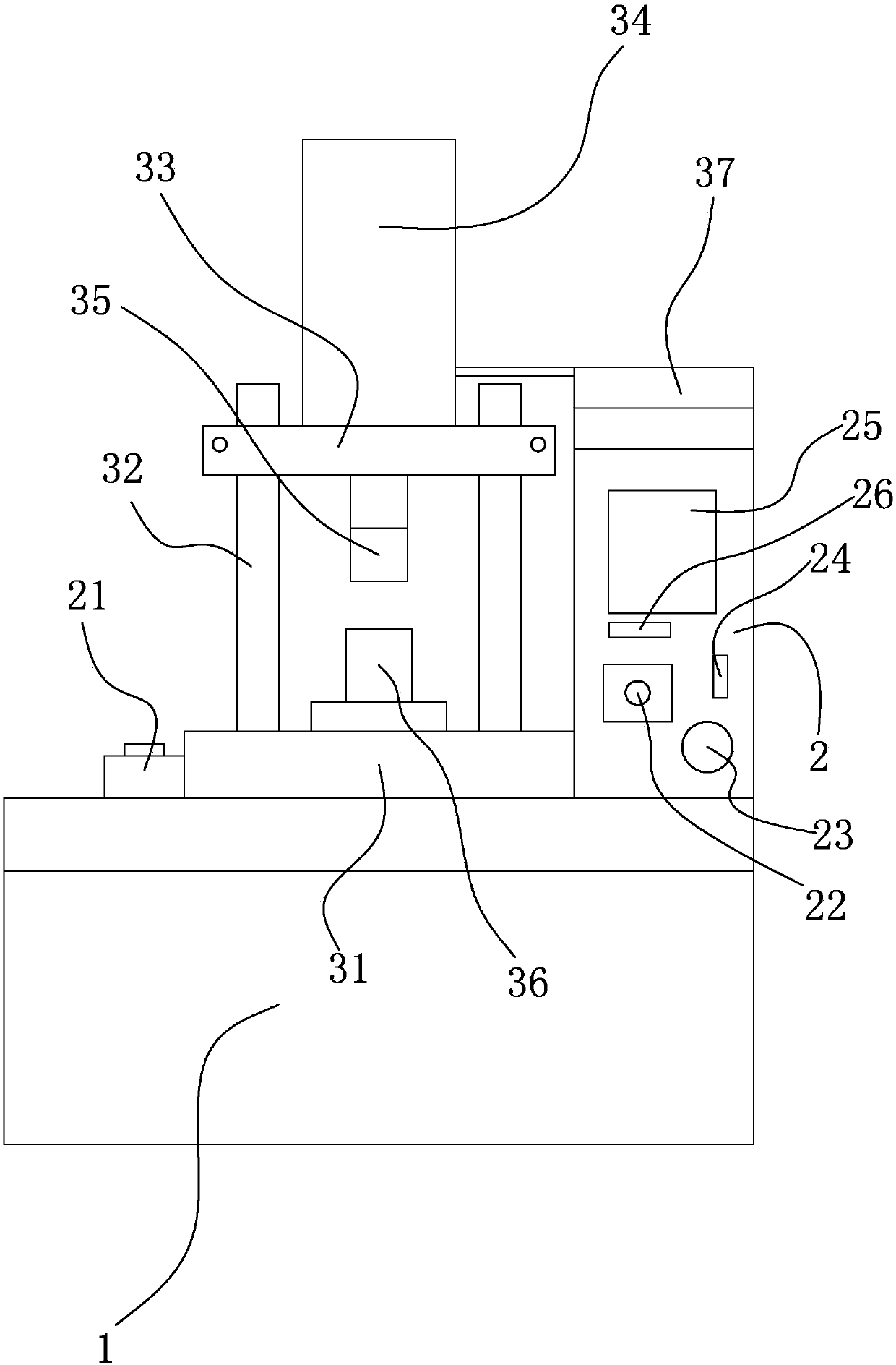
[0013] refer to figure 1 , a rotor duplex finale assembly production line, including a finale device, a conveying device, a baffle press-fitting device and a commutator press-fitting device, the finale device includes an organic base 1, and a finale shaft mechanism is fixedly arranged above the base 1, Press the rotating shaft into the iron core through the finale mechanism, the finale mechanism is electrically connected to the controller 2, and the finale mechanism is controlled by the controller 2, the controller 2 is arranged on the right side of the finale mechanism, and the controller 2 includes a first double switch 21 And the second double switch 22, the first double switch 21 and the second double switch 22 are connected in series, the first double switch 21 is arranged on the left side of the finale mechanism, the second double switch 22 is arranged on the controller 2, the second A double switch 21 and a second double switch 22 are located on both sides of the finale...


PUM


Abstract

The invention relates to the field of rotor assembly, and discloses a rotor two-gang pressure shaft assembly line. An operator puts a preinstalled rotating shaft and an iron core to a lower die head,and the two hands respectively press down a first ganged switch and a second ganged switch; a controller controls a control value; the control valve controls a pressure shaft cylinder; the pressure shaft cylinder drives an upper die head to press down in alignment with the lower die head, and the rotating shaft is pressed into the iron core, so that manual assembly is avoided, the takt time is fast, the production efficiency is high and the production cost is low; the first ganged switch and the second ganged switch are respectively arranged at the two sides of a pressure shaft mechanism, theoperator needs to synchronously press down the first ganged switch and the second ganged switch and then the pressure shaft mechanism can move, so as to ensure that the hands of the operator leave thelower die head to prevent the hands from being crushed.

Description

technical field [0001] The invention relates to the field of rotor assembly, in particular to a rotor duplex finale shaft assembly production line. Background technique [0002] The rotor is the key part of the motor. The rotor is composed of parts such as the rotating shaft and the iron core. In the assembly process of the rotor, the rotating shaft needs to be pressed into the iron core respectively. The pressing of the rotating shaft in the prior art is done manually. This method is inefficient. Contents of the invention [0003] In order to overcome the deficiencies of the prior art, the present invention provides a rotor duplex finale assembly production line, which eliminates manual assembly, has fast production rhythm, high production efficiency and low production cost. [0004] The technical solution adopted by the present invention to solve its technical problems: [0005] A rotor duplex finale assembly production line, including a finale device, a conveying devi...

Claims


Application Information

Patent Timeline
Patent Type & Authority Applications(China)
IPC IPC(8): H02K15/02
Inventor 刘国银
Owner 刘国银
Why Eureka
Eureka Blog
Learn More