Downhole life-saving equipment

A technology of life-saving equipment and life-saving devices, which is applied in the direction of life-saving equipment, respiratory protection containers, etc., can solve the problems of increased burden on the fire brigade, difficulty in quick positioning, and incomplete functions, so as to reduce the difficulty of rescue, widen the rescue range, and improve the survival rate Effect

Active Publication Date: 2018-01-19
季松石
View PDF7 Cites 4 Cited by
  • Summary
  • Abstract
  • Description
  • Claims
  • Application Information

AI Technical Summary

Problems solved by technology

[0002] The underground lifesaving devices in the prior art have the following problems: 1. Most of the deep wells are located in rural fields, and the best golden time for life-saving is missed due to the time delay caused by receiving the police and driving into the rescue.
2. Existing life preservers are large in size, heavy in weight, incomplete in function, and are manually operated. Rescue must rely on the fire brigade. It is difficult to save people, and it is even more difficult to locate quickly
3. Machine calibration requires the joint efforts of many people, which is cumbersome to operate, high in cost, time-consuming and labor-intensive
4. There are many rescuers and the area is large. The key is that it cannot be located at one time, and it will not be able to save a life and save a family in time, which brings helplessness to the firefighters. And put an unnecessary burden on the fire brigade

Method used


Image

  • Downhole life-saving equipment
  • Downhole life-saving equipment
  • Downhole life-saving equipment

Examples


Embodiment Construction

[0023] In order to deepen the understanding of the present invention, the present invention will be further described below in conjunction with the embodiments and accompanying drawings. The embodiments are only used to explain the present invention and do not constitute a limitation to the protection scope of the present invention.

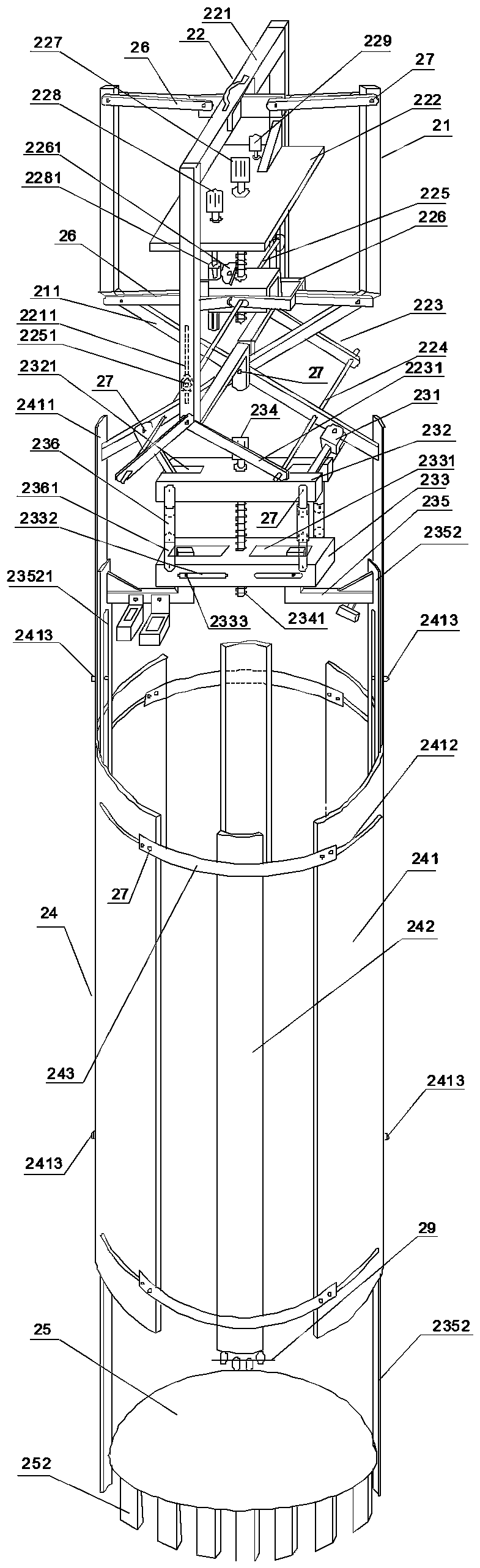
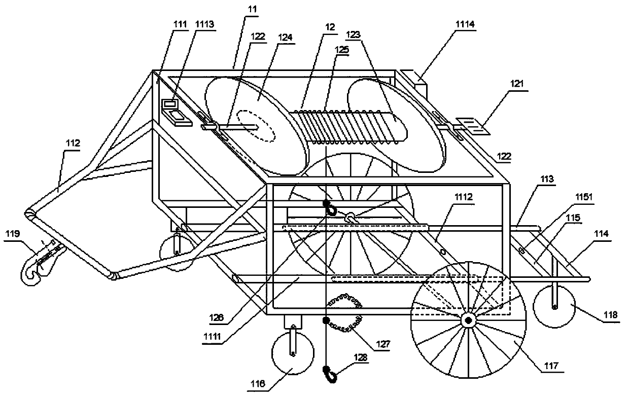
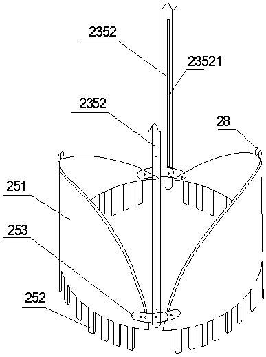
[0024] Such as figure 1 and figure 2 Shown, a kind of downhole life-saving equipment, comprises above-ground hoisting vehicle and downhole life-saving device, and down-hole life-saving device comprises pincer type extension control X-frame 21, hanger 22, pocket bottom automatic control device 23, bottomless telescopic barrel 24 and pocket bottom clip device 25, The pincer type extension control X frame 21 is to be formed by two mechanical arms 211 cross-hinged through the live pin 27, the top of the hanger 22 is hinged with the upper part of the pincer type extension control X frame 21 through the connecting rod 26, the bottom of the hanger fram...


PUM


Abstract

The invention discloses downhole life-saving equipment. The downhole life-saving equipment comprises a ground hoisting crane and an underground life preserver which is connected with the ground hoisting crane. The underground life preserver comprises a clamp-type stretching control X frame, a hanging bracket, a bottomed self-control device, a bottomless telescopic barrel and a bottomed clamp device. The clamp-type stretching control X frame is formed by hinging two mechanical arms in a crossed mode. The top of the hanging bracket is hinged to the upper portion of the clamp-type stretching control X frame through a connecting rod. The lower portion of the hanging bracket is hinged to the crossed position of the two mechanical arms. The bottomed self-control device is located below the clamp-type stretching control X frame and is further hinged to the lower ends of the two mechanical arms. The lower ends of the two mechanical arms are further fixedly connected with the bottomless telescopic barrel. The upper portion of the bottomless telescopic barrel is connected with the bottomed self-control device, and the bottom of the bottomless telescopic barrel is fixedly connected with the top of the bottomed clamp device. The life-saving equipment is wide in life-saving range, efficiency can be improved and cost can be reduced; the life-saving difficulties are lowered, and the burdens of firemen are relieved; original manual operation is changed into automation at one step, rescue can be conducted immediately when the equipment comes, the rescue does not have to depend on fire brigades, and local people can carry out rescue in time.

Description

technical field [0001] The invention relates to underground rescue equipment, in particular to an underground lifesaving equipment. Background technique [0002] The underground lifesaving device in the prior art has the following problems: 1. Deep wells are mostly located in rural fields, and the best golden time for lifesaving is missed due to the time delay caused by receiving the police and driving into the rescue. 2. Existing life preservers are large in size, heavy in weight, incomplete in function, and are manually operated, so rescue must rely on the fire brigade, making it difficult to save people and even more difficult to quickly locate them. 3. Machine calibration requires the joint efforts of many people, which is cumbersome to operate, high in cost, and time-consuming. 4. There are many rescuers and the area is large. The key is that it cannot be located at one time, and it will not be able to save a life and save a family in time, which brings helplessness to...

Claims


Application Information

Patent Timeline
Patent Type & Authority Applications(China)
IPC IPC(8): A62B99/00
Inventor 季松石陈天琪赵芳丛小利
Owner 季松石
Why Eureka
Try Eureka