Vibration type auto parts stamping device and method for stamping using the same

A technology of auto parts and stamping devices, which is applied in the field of vibrating auto parts stamping devices, can solve difficult problems such as improving the forming accuracy of high-strength steel or aluminum alloys or rebound defects, reducing vibration effects, and loosening of sheets, so as to avoid noise And mold collision wear, avoid rebound phenomenon, avoid the effect of wrinkling

Inactive Publication Date: 2019-06-25
DALIAN UNIV OF TECH
View PDF4 Cites 0 Cited by
  • Summary
  • Abstract
  • Description
  • Claims
  • Application Information

AI Technical Summary

Problems solved by technology

For stamping parts, if vibration occurs at the beginning of stamping, the sheet will loosen because it has not fully touched the mold when it is just stamped, which will lead to wrinkling of the sheet
Therefore, it is difficult to solve the problem of improving the forming accuracy of high-strength steel or aluminum alloy or springback defects when stamping is accompanied by the work of the exciter.
[0003] At present, it has appeared to eliminate the internal residual stress of the workpiece through vibration aging, thereby eliminating the springback phenomenon of automobile steel or aluminum after plastic forming, but this device and method simply transfers the processed parts from the mold to the vibration table Vibration aging treatment, although part of the residual stress can be eliminated, but in the process of transferring to fixing on the vibrating table, part of the rebound phenomenon has appeared, thus weakening the vibration effect

Method used


Image

  • Vibration type auto parts stamping device and method for stamping using the same
  • Vibration type auto parts stamping device and method for stamping using the same

Examples


Embodiment 1

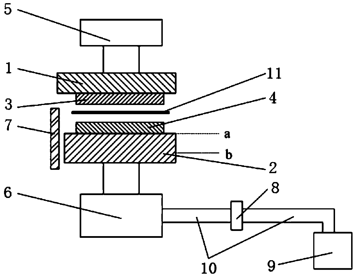
[0029] Such as figure 1 Shown, a kind of vibratory auto parts stamping device comprises an upper workbench 1 and a lower workbench 2 which are arranged vertically oppositely, the lower surface of the upper workbench 1 is provided with an upper die 3, and the lower workbench The upper surface of 2 is provided with a lower mold 4 corresponding to the upper mold 3, and the upper workbench 1 is provided with an upper hydraulic cylinder 5 that drives the upper workbench 1 to move vertically. The table 2 is provided with a lower hydraulic cylinder 6 that drives the lower worktable 2 to move in the vertical direction, a damper 7 is provided on the downward movement track of the upper worktable 1, and the lower hydraulic cylinder 6 is overflowed by electromagnetic The valve 8 communicates with the hydraulic source 9;

[0030] Both the lower hydraulic cylinder 6 and the electromagnetic overflow valve 8 and the electromagnetic overflow valve 8 and the hydraulic source 9 are communicate...

Embodiment 2

[0034] A method of stamping using the vibrating auto parts stamping device described in Example 1. In this example, DP780 steel plate is selected as the sheet material 11 to be stamped, with a tensile strength of about 780MPa and a thickness of 1.0mm. Taking the side wall of an automobile as an example , with the following steps:

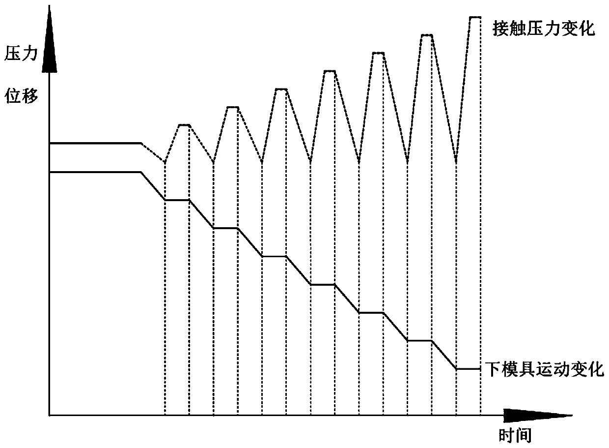
[0035] S1. The lower hydraulic cylinder 6 places the lower workbench 2 at the top dead center a of the lower workbench 2 and keeps it still;

[0036] S2. The blank 11 to be stamped is placed between the upper mold 3 and the lower mold 4, and the upper hydraulic cylinder 5 drives the upper worktable 1 to drive the upper mold 3 to move downward, and the stamping process starts;

[0037] S3. When the upper mold 3 descends before closing with the lower mold 4, control the oil pressure of the lower hydraulic cylinder 6 to be lower than the peak oil pressure of the upper hydraulic cylinder 5, thereby ensuring that the upper workbench 1 When in contact wi...


PUM

PropertyMeasurementUnit
tensile strengthaaaaaaaaaa
thicknessaaaaaaaaaa

Abstract

The invention discloses a vibration type stamping device for automobile parts and a method for stamping through the same. The vibration type stamping device for the automobile parts comprises an upperworktable and a lower worktable which are oppositely arranged in the vertical direction. An upper die is arranged on the lower surface of the upper worktable, and a lower die corresponding to the upper die is arranged on the upper surface of the lower worktable. An upper hydraulic oil cylinder for driving the upper worktable to make movement in the vertical direction is arranged on the upper worktable, and a lower hydraulic oil cylinder for driving the lower worktable to make movement in the vertical direction is arranged on the lower worktable. A damper is arranged on the downward movement track of the upper worktable. The lower hydraulic cylinder communicates with a hydraulic source through an electromagnetic overflow valve. Abrasion to the die faces due to vibration is avoided, the forming quality of chambers and edges are further promoted, the full forming effect is achieved, and the precision of the parts is promoted; noise and die collision abrasion caused by mechanical vibration are avoided; the defects of corrugating and the like in the stamping process are avoided; and the springback phenomenon in the transferring process is avoided.

Description

technical field [0001] The invention relates to the technical field of stamping and forming of metals, and in particular provides a vibrating stamping device for auto parts and a stamping method using the device. Background technique [0002] Stamping forming technology is one of the key forming and manufacturing technologies of auto parts. Especially in order to meet the technical requirements of automobile lightweight and safety, high-strength steel and aluminum alloy stamping parts have been widely used, but with the continuous improvement of the strength and performance of automobile steel Improvement, the existing stamping equipment is prone to insufficient forming accuracy or springback phenomenon, especially for complex stamping parts, the stamping is often not in place near the chamfer and edge. Regarding the aspect of suppressing springback, the invention patent publication number: CN106345882A "A Vibration-Assisted Aircraft Skin Stretch Forming and Springback Suppr...

Claims


Application Information

Patent Timeline
Patent Type & Authority Patents(China)
IPC IPC(8): B21D22/02B21D37/12
Inventor 常颖王宝堂李晓东余树洲杨晓莉王宁韩硕王治文
Owner DALIAN UNIV OF TECH
Why Eureka
Try Eureka