
A simple metal stranded wire branching device

A branching device and technology of twisted wire, applied in the field of metal twisted wire branching device, can solve problems such as inconvenient operation, long branching time, slow branching speed, etc., achieve fast and effective branching and collection, improve The effect of resource utilization and work efficiency improvement

Active Publication Date: 2018-12-18
苏州冠普电子有限公司
View PDF9 Cites 0 Cited by
  • Summary
  • Abstract
  • Description
  • Claims
  • Application Information

AI Technical Summary

Problems solved by technology

[0003] The wire and cable industry pays more and more attention to the control of production efficiency and production cost. The improvement of production efficiency and the control of production cost determine the economic benefits of the wire and cable industry. In order to improve economic benefits, wire and cable companies generally use metal stranded wires The device is used to re-use the scrapped metal twisted wire. At present, the metal twisted wire splitting device used in China not only has complex structure, large volume, inconvenient operation, slow splitting speed, and long splitting time. , high energy consumption and other defects, and it is bulky and not easy to move

Method used


Image

  • A simple metal stranded wire branching device
  • A simple metal stranded wire branching device
  • A simple metal stranded wire branching device

Examples


Embodiment

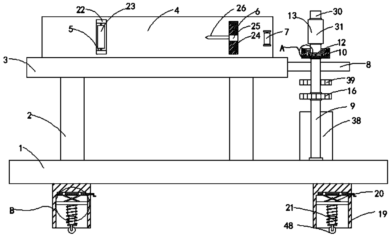
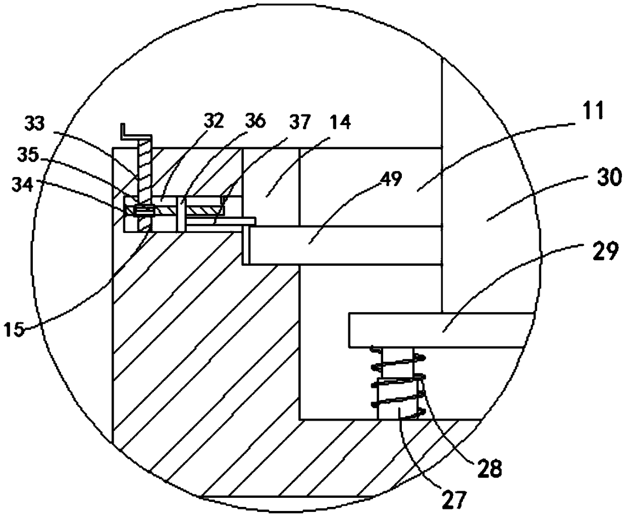
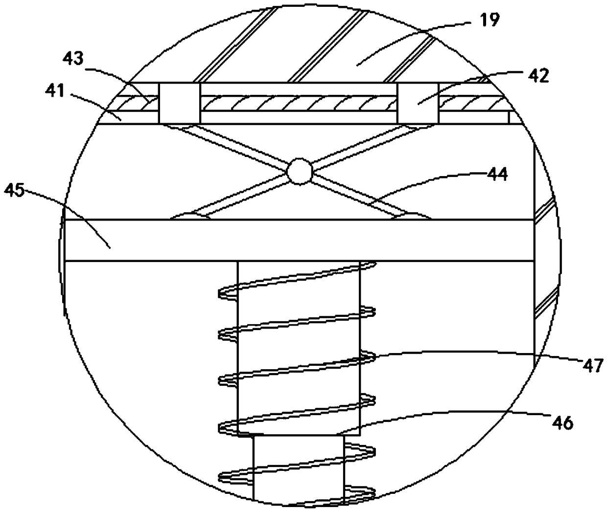
[0024] Such as Figure 1-5 As shown, a simple metal twisted wire branching device includes a base 1, a plurality of support columns 2 are arranged on the base 1, a console 3 is arranged on the support column 2, and two walking blocks are horizontally arranged on the console 3. Wire plate 4, a straightening mechanism 5 is provided between the two wiring boards 4, a wire dividing mechanism 6 is provided between the two wiring boards 4, and the wire dividing mechanism 6 is arranged on the wire routing plate 4 away from the straightening mechanism 5 On one end, guide rollers 7 are provided on the opposite side walls of the two wiring boards 4, and the guide rollers 7 are arranged on the end of the wiring board 4 close to the branching mechanism 6, and the side wall of the console 3 is close to the end of the guide rollers 7. Two horizontal plates 8 are connected to the top, and the two horizontal plates 8 are provided with a first through hole communicating up and down, and a rota...


PUM


Abstract

The invention belongs to the technical field of metal twisted-wire wire-dividing devices and particularly relates to a simple-type metal twisted-wire wire-dividing device which comprises a base. The base is provided with a plurality of supporting columns, a control platform is arranged on the supporting columns and is horizontally provided with two wire distribution plates, a pressing-straightening mechanism and a wire-dividing mechanism are arranged between the two wire distribution plates, and the wire-dividing mechanism is arranged at the ends, away from the pressing-straightening mechanism, of the wire-walking plates. The opposite side walls of the two wire distribution plates are both provided with direction guide rollers, and the direction guide rollers are arranged at the ends, close to the wire-dividing mechanism, of the wire-walking plates. The side wall of the end, close to the direction guide rollers, of the control platform is connected with two horizontal plates, and the two horizontal plates are both provided with vertically-interconnected first through-holes, and each first through-hole is internally provided with a rotating rod in a penetrated manner, the lower endof each rotating rod is rotatably connected with the base, and the upper end of each rotating rod is fixedly connected with a connection seat. The simple-type metal twisted-wire wire-dividing device has the advantages that the twisted-wire can be rapidly and effectively divided and rolled through the simple-type metal twisted-wire wire-dividing device, and the wire-dividing device is convenient tomove.

Description

technical field [0001] The invention belongs to the technical field of metal twisted wire branching devices, in particular to a metal twisted wire branching device. Background technique [0002] In the broad sense, wires and cables are also referred to as cables for short. In the narrow sense, cables refer to insulated cables, which can be defined as a collection composed of the following parts: one or more insulated cores, and their respective possible coatings. Protective layer and outer sheath, the cable may also have additional uninsulated conductors. [0003] The wire and cable industry pays more and more attention to the control of production efficiency and production cost. The improvement of production efficiency and the control of production cost determine the economic benefits of the wire and cable industry. In order to improve economic benefits, wire and cable companies generally use metal stranded wires The device is used to re-use the scrapped metal twisted wire...

Claims


Application Information

Patent Timeline
Patent Type & Authority Patents(China)
IPC IPC(8): B21F13/00B21C47/02B21C47/28B21C47/26
Inventor 王兴松许飞云罗翔戴挺章功国
Owner 苏州冠普电子有限公司
Learn More