
Gear rack tail end approximate straight-line composite grabbing robot finger device

A robot finger, approximate straight line technology, applied in manipulators, chucks, manufacturing tools, etc., can solve the problem that the linear translation of the end finger segment cannot be realized, the dependence on the cooperative control programming of the robot arm is increased, and the adaptive envelope grasping cannot be realized. To achieve the effect of reducing programming requirements, low cost, simple and compact structure

Inactive Publication Date: 2018-01-19
TSINGHUA UNIV
View PDF8 Cites 7 Cited by
  • Summary
  • Abstract
  • Description
  • Claims
  • Application Information

AI Technical Summary

Problems solved by technology

Its disadvantage is that the device cannot realize the function of adaptive envelope grabbing
The disadvantage of this device is that in the initial stage of grasping by the flat clip, the end of the finger moves in a circular arc—the end circular arc moves in translation, which cannot achieve the effect of linear translation of the end finger segment. , requires good cooperation of the robotic arm, thus increasing the dependence on the programming of the cooperative control of the robotic arm

Method used


Image

  • Gear rack tail end approximate straight-line composite grabbing robot finger device
  • Gear rack tail end approximate straight-line composite grabbing robot finger device
  • Gear rack tail end approximate straight-line composite grabbing robot finger device

Examples


Embodiment Construction

[0036] The specific structure and working principle of the present invention will be further described in detail below in conjunction with the accompanying drawings and embodiments.

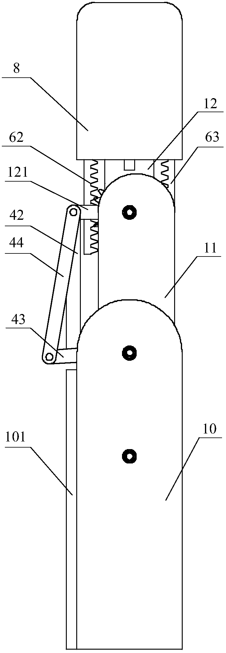
[0037] An embodiment of a rack and pinion end approximate straight line compound grasping robot finger device designed by the present invention, such as Figure 1 to Figure 7 As shown, it includes base 10, first finger segment 11, second finger segment 12, proximal joint shaft 31, distal joint shaft 32, motor 2, transmission mechanism, first connecting rod 41, second connecting rod 42, third Connecting rod 43, fourth connecting rod 44, second finger segment connecting rod 121, first rotating shaft 51, second rotating shaft 52, third rotating shaft 53, first spring 71, first limiting protrusion 73 and second limiting Protrusion 74; the proximal joint shaft 31 is sleeved in the base 10, the first finger segment 11 is sleeved on the proximal joint shaft 31, and the distal joint shaft 32 is sleeved i...


PUM


Abstract

The invention relates to a gear rack tail end approximate straight-line composite grabbing robot finger device and belongs to the technical field of robot hands. The gear rack tail end approximate straight-line composite grabbing robot finger device comprises a base, two finger sections, two joint shafts, a motor, a plurality of connecting rods, a gear, two racks, two springs, two limiting convexblocks and the like. The device realizes a straight-line flat clamping and self-adaptive composite grabbing mode, can flatly move the second finger section to clamp an object, and also can rotate thefirst finger section to touch the object and then rotate the second finger section to envelope the objects with different shapes and sizes; in the stage of flatly moving the second finger section to clamp the object, the tail end of the second finger section still maintains approximate straight-line track motion, so the gear rack tail end approximate straight-line composite grabbing robot finger device is suitable for grabbing flat plate objects on a workbench and reduces the mechanical arm programming requirements; and only one motor is used for driving two joints, so the gear rack tail end approximate straight-line composite grabbing robot finger device is simple and compact in structure and low in cost, does not need a complex sensing and control system, and is suitable for occasions that the robot needs to grab and operate the objects with different sizes.

Description

technical field [0001] The invention belongs to the technical field of robot hands, and in particular relates to a structural design of a near-line compound grasping robot finger device at the end of a rack and pinion. Background technique [0002] With the development of automation technology, robot technology has ushered in a new peak. As a kind of end effector of robot, the robot hand has attracted more attention, and more and more researches have been done on the robot hand. Parallel clamping and grasping at the end of the robot finger is a common grasping method. The terminal finger segment always maintains a fixed posture relative to the base during the movement. During the grasping process, two or more fingers opposite to each other Two or more sides of the finger touch the object and exert a gripping force. The elastic deformation material on the finger surface is used to obtain a soft finger surface to improve the stability of the grip. This parallel clamping device...

Claims


Application Information

Patent Timeline
IPC IPC(8): B25J15/00B25J15/02B25J15/12
Inventor 姚守菊张文增徐向荣
Owner TSINGHUA UNIV
Learn More