
Die locking mechanism and method for two-plate injection molding machine to bear spiral pairs to synchronously follow movable template

A technology of moving platen and injection molding machine, which is applied in the field of clamping mechanism of two-platen injection molding machine bearing screw pair synchronously following the moving platen, which can solve the problems of high equipment manufacturing cost, troublesome mold adjustment, difficult equipment maintenance, etc., and achieve manufacturing cost And the effect of low maintenance cost, shortened production cycle, and shortened mold clamping stroke

Pending Publication Date: 2018-01-19
SOUTH CHINA UNIV OF TECH +1
View PDF15 Cites 2 Cited by
  • Summary
  • Abstract
  • Description
  • Claims
  • Application Information

AI Technical Summary

Problems solved by technology

Its mold shifting and mold locking are separated. The mold shifting uses a small oil cylinder, which moves fast but with a small force. After moving to the right position, the mold closing uses a mold locking cylinder with a small stroke. When closing the mold, it uses the lock brake Lock or the nut clamps the tie rod, and then applies the clamping force through the clamping cylinder to close the mold, but this method has poor stability and is troublesome to adjust the mold
[0005] The mold clamping mechanism of the outer circulation is to fix the mold clamping cylinder on the moving platen. When the mold is moved, the mold clamping cylinder moves along with it. Injection molding machine axial distance increased
In addition, the oil exchange inside adopts external circulation, and the unused oil is discharged to the oil tank when the mold is moved, and the other end also absorbs oil from the oil tank, which increases the pipeline loss and energy consumption value
[0006] The mold clamping mechanism of the internal circulation is controlled by a valve in the piston of the clamping device, which separates the cylinder into a high-pressure chamber and a storage chamber. The oil can be circulated and exchanged when the mold is moved, but the internal circulation increases the oil cylinder. length, and requires high precision, the equipment manufacturing cost is high, and the equipment maintenance is difficult

Method used


Image

  • Die locking mechanism and method for two-plate injection molding machine to bear spiral pairs to synchronously follow movable template
  • Die locking mechanism and method for two-plate injection molding machine to bear spiral pairs to synchronously follow movable template
  • Die locking mechanism and method for two-plate injection molding machine to bear spiral pairs to synchronously follow movable template

Examples


Embodiment 1

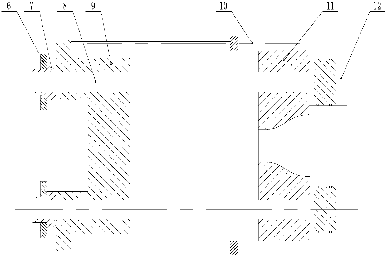
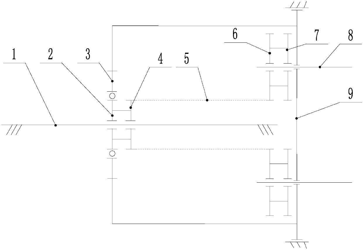
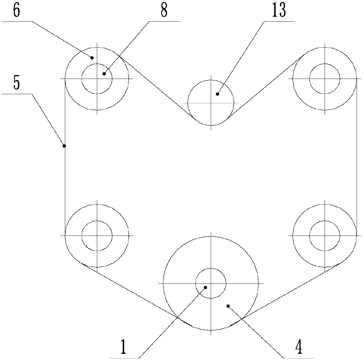
[0031] In this embodiment, a clamping mechanism for a two-platen injection molding machine that carries a screw pair and follows a moving template synchronously, such as figure 1 As shown, it includes a matched movable template 9 and a fixed template 11. The movable template and the fixed template are connected by four pull rods 8. On each pull rod, an end that is positioned outside the movable template is provided with a clamping nut 7. One end is provided with clamping oil cylinder 12, and clamping oil cylinder is installed on the outside of fixed formwork, and pull rod and clamping bearing nut form the first rolling screw pair; figure 2 As shown, a support seat 3 is provided on the outside of the movable formwork, and a second scroll screw pair is provided on the support seat. The second scroll screw pair includes a screw 1 and a screw nut 2. The screw and the pull rod are arranged in parallel and fixed on the frame. , the screw nut is arranged on the screw rod, and the ou...

Embodiment 2

[0039] This implementation is a clamping mechanism for a two-platen injection molding machine that carries a screw pair and follows the moving template synchronously. Compared with Example 1, the difference lies in: Figure 4 As shown, there are four tie rods, and each tie rod is connected with the same clamping oil cylinder, and the clamping oil cylinder is embedded in the fixed template in a circular structure. In this structural form, the fixed platen and the movable platen are in a circular shape, a plurality of tie rods are distributed along the circumferential direction of the top platen, and the clamping cylinder is in the shape of a ring and embedded in the fixed platen. When the tonnage of the injection molding machine is large, Adopting this structural form can significantly increase the area of ​​the mold clamping cylinder, thereby providing a large mold clamping force at a lower system pressure.


PUM


Abstract

The invention discloses a die locking mechanism and method for a two-plate injection molding machine to bear spiral pairs to synchronously follow a movable template. In the mechanism, the movable template and a fixed template are connected through pull rods, the ends, located on the outer side of the movable template, of the pull rods are provided with die locking bearing nuts, the other ends of the pull rods are provided with die locking oil cylinders, and a first rolling spiral pair is formed by each pull rod and the corresponding die locking bearing nut. Supporting bases are arranged on theouter side of the movable template and provided with second rolling spiral pairs. A following synchronous belt wheel assembly is arranged between each second rolling spiral pair and the correspondingfirst rolling spiral pair. According to the method, die moving oil cylinders drive the movable template to conduct the die opening or closing action, the movable template drives the second spiral rolling spiral pairs to act, and the second rolling spiral pairs drive the first rolling spiral pairs to synchronously run through the following synchronous belt wheel assemblies. According to the die locking mechanism, usage of a gate plate and a hooping nut can be omitted, a special die adjusting device does not need to be arranged, and the die locking mechanism can adapt to different die thicknesses and is flexible in usage.

Description

technical field [0001] The invention relates to the field of mold clamping equipment for injection molding machines, in particular to a mold clamping mechanism and method for a two-platen injection molding machine carrying a screw pair and synchronously following a moving template. Background technique [0002] The mold clamping device of the traditional injection molding machine is a three-plate type, which consists of a head plate, a second plate and a tail plate. Generally, the head plate is a fixed plate, and the second plate is connected to the tail plate through a tie rod. The clamping oil rainbow installed on the tail plate drives the second plate. Perform mold opening and closing actions. After the mold is closed in place, a large clamping force is generated through the force amplification of the toggle. This structure leads to a relatively fixed clamping stroke. When the tonnage is large, the weight of the clamping system quite big. Compared with the traditional th...

Claims


Application Information

Patent Timeline
Patent Type & Authority Applications(China)
IPC IPC(8): B29C45/68
Inventor 瞿金平
Owner SOUTH CHINA UNIV OF TECH
Learn More