
Variable structure turboshaft engine gas intake system

A turboshaft engine and air intake system technology, which is applied in the direction of engine components, machine/engine, turbine/propulsion device air intake, etc., can solve the problem of circumferential uneven sealing, difficulty, memory alloy does not meet the requirements, etc. problems, to achieve the effect of improving aerodynamic efficiency and reducing height

Active Publication Date: 2018-01-19
NANJING UNIV OF AERONAUTICS & ASTRONAUTICS
View PDF5 Cites 5 Cited by
  • Summary
  • Abstract
  • Description
  • Claims
  • Application Information

AI Technical Summary

Problems solved by technology

This idea is ingenious, but it is very difficult to realize. The installation of the worm device adds a lot of complexity to the system structure. At the same time, there are circumferential unevenness and sealing problems, and the current research on memory alloys still does not meet the requirements. level, therefore, the engineering application of this concept is extremely difficult

Method used


Image

  • Variable structure turboshaft engine gas intake system
  • Variable structure turboshaft engine gas intake system
  • Variable structure turboshaft engine gas intake system

Examples


Embodiment Construction

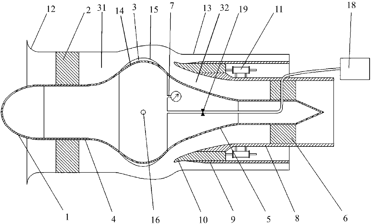
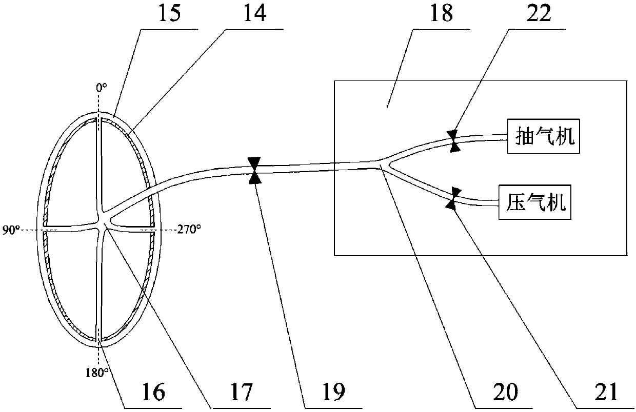
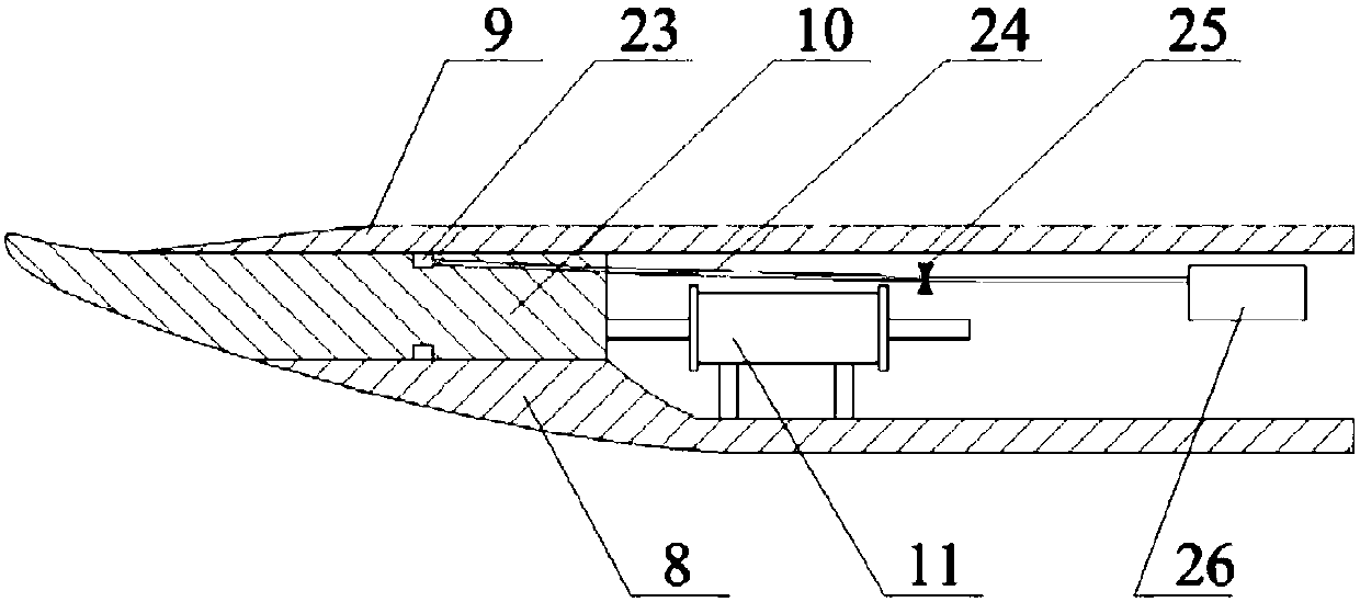
[0022] see figure 1 As shown, the invention discloses a turboshaft engine air intake device, which includes a center body assembly, a wedge assembly and a casing assembly. The casing assembly is the shell of the integral air intake device, including an outer cylinder 13 surrounding the central body assembly and a double-button lip section 12 located at the front of the outer cylinder 13 . The central body assembly includes a front fairing 1, an annular air chamber 3, a central body front section 4 extending forward from the annular air chamber, a central body rear section 5 extending backward from the annular air chamber, connecting and fixing the outer cylinder 13 and The front support section 2 of the front section 4 of the central body is connected and fixed to the outer cylinder 13 and the rear support section 6 and the pressure monitor 7 of the rear section 5 of the central body. Among them, the annular air chamber 3 adopts an integral structure, with a metal structure a...


PUM


Abstract

The invention discloses a turboshaft engine gas intake system. The gas intake system comprises a center body assembly, a wedge assembly and a casing assembly. A flexible and deformable annular gas chamber is embedded in the center body assembly; a wedge capable of moving in the axial direction is designed at the same time; and according to the work environment and the work state of an engine, themolded surface of a gas chamber and the axial position of the wedge are adjusted. When a helicopter works in an unclean air environment of dust sand and the like, the height of the gas chamber is increased, the position of the wedge moves forwards, and the gas intake system is made to be in a high dust sand separation efficiency mode; and when the helicopter is in a cruising condition, the heightof the gas chamber is reduced, the position of the wedge moves backwards, and the gas intake system is made to work in a high pneumatic efficiency mode. By means of the turboshaft engine gas intake system, the problem that a traditional fixed geometric gas intake system can not consider both efficient sand discharging and high pneumatic performance of cruising is solved.

Description

[0001] The patent application for the present invention is a divisional application. The invention and creation name of the original application is: a turboshaft engine air intake device and its operation method; the application date is: November 09, 2016; the application number is 201610985841.1. technical field [0002] The invention relates to the field of aeroengine design, in particular to the air intake system of a turboshaft engine. Background technique [0003] my country is one of the countries with the largest desert area in the world. The desert is an arc-shaped belt stretching across the northwest, north and northeast lands. This arc-shaped desert belt is 600km wide from north to south and 4000km long from east to west. In the desert area, the desert covers an area of ​​1.49 million square kilometers, accounting for 15.5% of the country's land area. Due to the convenient take-off and landing of the helicopter, the requirements for the airport environment are rela...

Claims


Application Information

Patent Timeline
Patent Type & Authority Applications(China)
IPC IPC(8): F02C7/042F02C7/05F02C7/057
CPCF02C7/04F02C7/05
Inventor 谭慧俊凌棫陈昊黄河峡张悦孙姝
Owner NANJING UNIV OF AERONAUTICS & ASTRONAUTICS
Learn More