An optical lever measuring device

A measuring device and optical lever technology, applied in the direction of measuring devices, optical devices, instruments, etc., can solve the problems of unfavorable laboratory utilization efficiency, large laboratory space, low measurement accuracy, etc., to improve space utilization, operation and performance. The effect of convenient reading and high measurement efficiency

Active Publication Date: 2019-12-03
WEIFANG UNIVERSITY
View PDF7 Cites 0 Cited by
  • Summary
  • Abstract
  • Description
  • Claims
  • Application Information

AI Technical Summary

Problems solved by technology

The magnification of the optical lever is proportional to the distance between the mirror and the scale. The greater the distance between the mirror and the scale, the greater the magnification of the optical lever and the higher the measurement accuracy. However, due to the limited space of the university laboratory, the general distance is also It is one to two meters, such a steel wire with a diameter of about 0.3mm, under the action of a Newton force, the final reading change on the scale is only about half a millimeter, and the measurement accuracy is not high
[0005] 2. It is inconvenient to operate and read. The Young’s modulus measuring instrument adjusts the tension parameters and observes the scale value at different positions. The experimenter needs to move back and forth at both ends, which affects the efficiency of the experiment, and cannot observe the process of the change of the reading when the tension changes.
[0006] 3. It is difficult to adjust the telescope, and it takes a long time to adjust the telescope so that the ruler presents a clear image in the telescope, and even the time to adjust the telescope is much longer than the specific measurement time
[0007] 4. It takes up a lot of laboratory space, which is not conducive to improving the utilization efficiency of the laboratory

Method used


Image

  • An optical lever measuring device
  • An optical lever measuring device
  • An optical lever measuring device

Examples


Embodiment 1

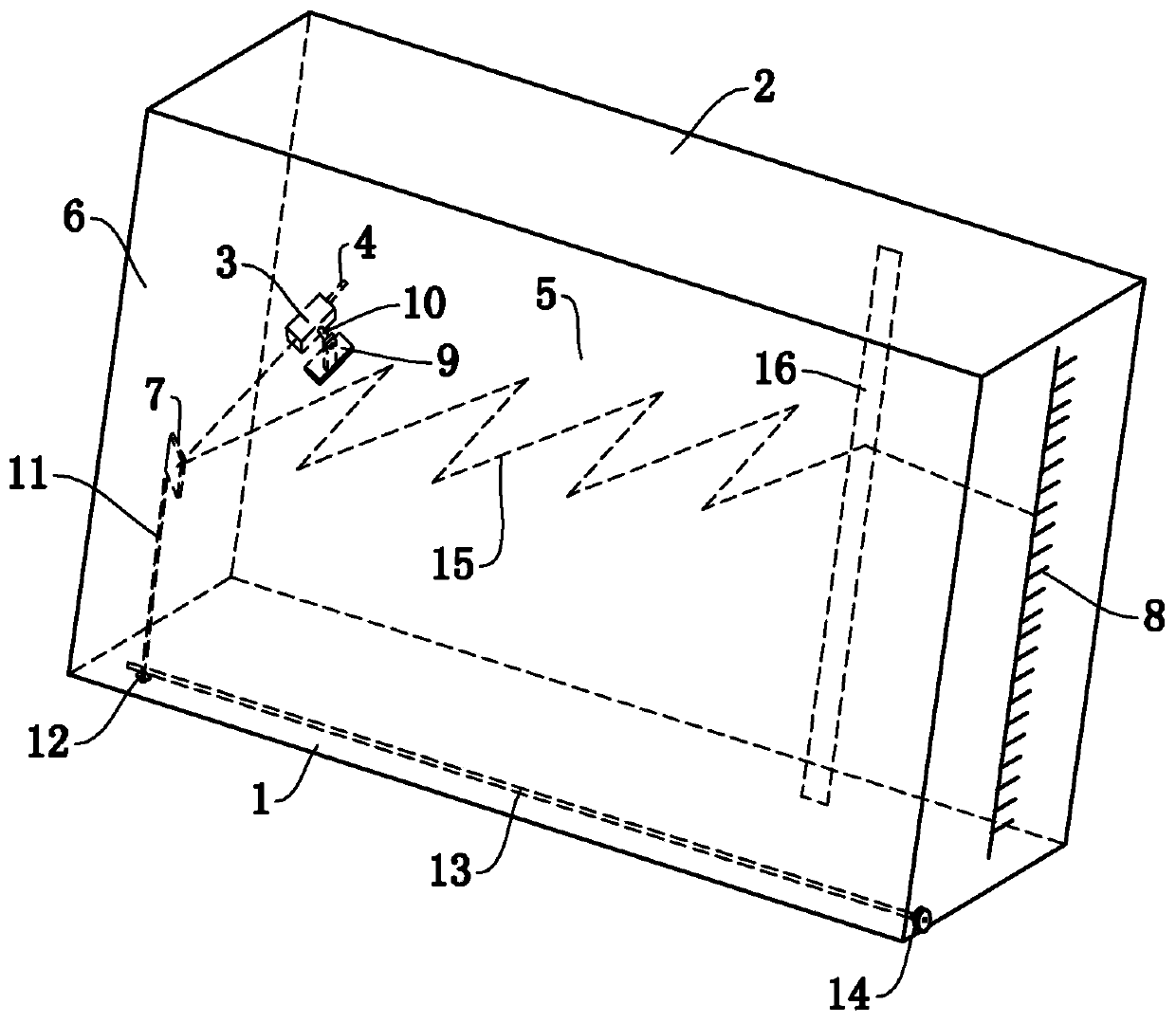
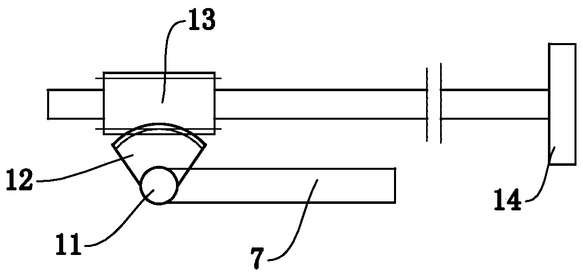
[0047] Such as Figure 1 to Figure 3 Commonly shown, a kind of optical lever measuring device, comprises base plate 1, top plate 2, laser device 3, support foot 4, the first reflection mirror 5 and the second reflection mirror 6 that are arranged parallel to each other, reflection mirror 7, display with scale Screen 8 and support 9, the first reflective mirror 5, the second reflective mirror 6 and the display screen 8 are all vertically arranged on the base plate 1, and the top plate 2 is arranged between the tops of the first reflective mirror 5 and the second reflective mirror 6 Between, the reflective surface of the first reflective mirror 5 and the reflective surface of the second reflective mirror 6 are oppositely arranged.

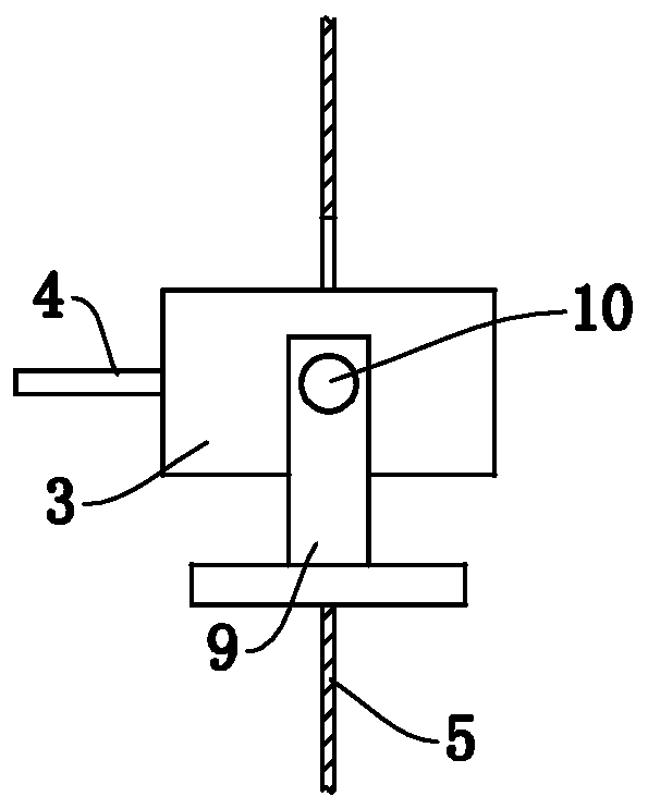
[0048] The support 9 is fixedly mounted on the first reflector 5, and a horizontal axis 10 is arranged between the laser 3 and the support 9. One end of the laser 3 is fixedly connected to the supporting foot 4, and the other end is a laser emitting ...

Embodiment 2

[0063] This embodiment is basically the same as Embodiment 1, the difference is that, as Figure 7 As shown, the top plate 2 is provided with a guide rail 18, of course, the guide rail 18 can also be installed on the base plate 1, the extension direction of the guide rail 18 is consistent with the extension direction of the first reflector 5, and the laser display position adjustment mirror 16 is slidably installed on the guide rail 18 on. In this way, the position of the laser display position adjustment mirror 16 can be changed conveniently, avoiding the problem that the laser light path deviates from the range of the laser display position adjustment mirror 16 due to changing the laser reflection angle.

[0064] The reflective surface of the laser display position adjustment mirror 16 is a plane, the guide rail 18 is provided with a slide block 19, an angle adjustment device 20 is provided between the laser display position adjustment mirror 16 and the slide block 19, and t...

Embodiment 3

[0068] This embodiment is basically the same as Embodiment 2, the difference is that, as Figure 9 As shown, the reflective surface of the laser display position adjustment mirror 16 is a vertically arranged cylindrical surface, and the laser inline display mirror 17 is not provided, so that the laser spot can be expanded in the horizontal direction of the display screen 8, which facilitates reading.

[0069] The optical lever measuring device provided by the embodiment of the present invention has high measurement accuracy; it is convenient to operate and read, and can observe the process of the change of the reading when the length of the object changes; the measurement efficiency is high; the occupied space is small, which is conducive to improving the space utilization of the laboratory Rate.


PUM


Abstract

The invention discloses an optical lever measuring device, and belongs to the physics experiment apparatus technical field; the optical lever measuring device comprises a base plate, a top plate, a laser, a leg, a first reflective mirror and a second reflective mirror arranged in parallel, a reflector, a display screen with scales and a support; the support is fixed on the first reflective mirror;a horizontal shaft is arranged between the laser and the first support; one end of the laser is fixedly connected with the leg, and the other end is a laser emission end; the reflector is fixed on acolumn vertical to the base plate; the column bottom is fixedly provided with a worm gear; the base plate is also provided with a worm engaged with the worm gear; the worm is horizontally arranged, and the worm end portion penetrates the display screen bottom; the worm penetrating end is fixedly provided with an adjusting turn button. The optical lever measuring device is convenient in operation and to read, high in measuring efficiency, small in occupation space, and the reading changing process can be observed when the object length changes, thus improving the laboratory space utilization rate.

Description

technical field [0001] The invention belongs to the technical field of physical experiment instruments, in particular to an optical lever measuring device. Background technique [0002] In various scientific experiments, it is often necessary to measure small changes in length. For example, measuring the Young's modulus of materials by stretching is one of the common ones. The traditional stretching method to measure the Young's modulus of metals uses the principle of optical levers. , the small elongation of the metal wire under the action of tension is amplified by the mirror light lever, and observed through the telescope and ruler placed in the distance. [0003] However, the above-mentioned optical lever measurement method has the following disadvantages: [0004] 1. The magnification of the optical lever is too small. The magnification of the optical lever is proportional to the distance between the mirror and the scale. The greater the distance between the mirror an...

Claims


Application Information

Patent Timeline
Patent Type & Authority Patents(China)
IPC IPC(8): G01B11/02
Inventor 周薇戴长志
Owner WEIFANG UNIVERSITY
Why Eureka
Try Eureka