Gas leakage source positioning method

A gas leakage and source localization technology, applied in measurement devices, instruments, mapping and navigation, etc., can solve the problems of high cost, high sensor cost, difficult implementation, etc., and achieve fast positioning speed, high positioning accuracy, and low constraints. Effect

Inactive Publication Date: 2018-01-19
IVOCMN SHANGHAI INTERNET OF THINGS TECH CO LTD
View PDF7 Cites 23 Cited by
  • Summary
  • Abstract
  • Description
  • Claims
  • Application Information

AI Technical Summary

Problems solved by technology

[0003] 1. Use small robots to search for leakage sources. This method has strong mobility and wide monitoring coverage. However, this method is costly and it is impossible to deploy a wide range of robots in the monitoring area;
[0004] 2. UAV is used to search and locate the leakage area to be tested. This method has high precision, but it requires high cost, poor versatility, and difficult to realize;
[0005] 3. Using high-resolution sensors, the monitoring data is sent back to the monitoring center for analysis and processing. Although this method can obtain data in time, there are problems of high sensor cost, large volume, and low monitoring and positioning accuracy.

Method used


Image

  • Gas leakage source positioning method
  • Gas leakage source positioning method
  • Gas leakage source positioning method

Examples


Embodiment Construction

[0038] In order to make the technical means, creative features, objectives and effects achieved by the present invention easy to understand, the present invention will be further elaborated below.

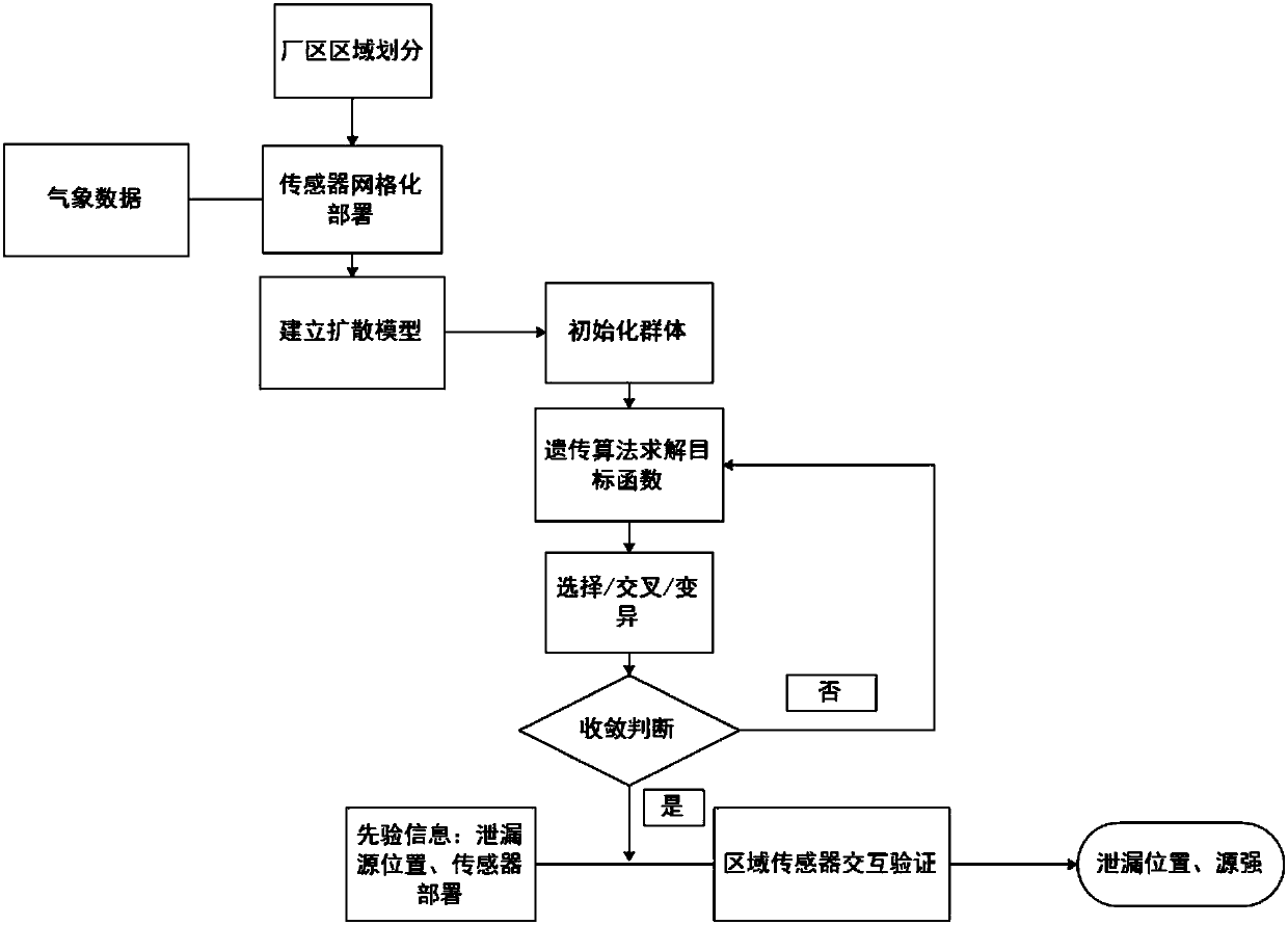
[0039] see figure 1 and figure 2 A method for locating a gas leakage source is shown, comprising the following steps:

[0040] 1) Monitoring plant area division and sensor node deployment: Divide the plant area into several rectangular areas of similar size. For any divided area, deploy sensors in a grid to ensure that there are corresponding sensors in different downwind directions ;

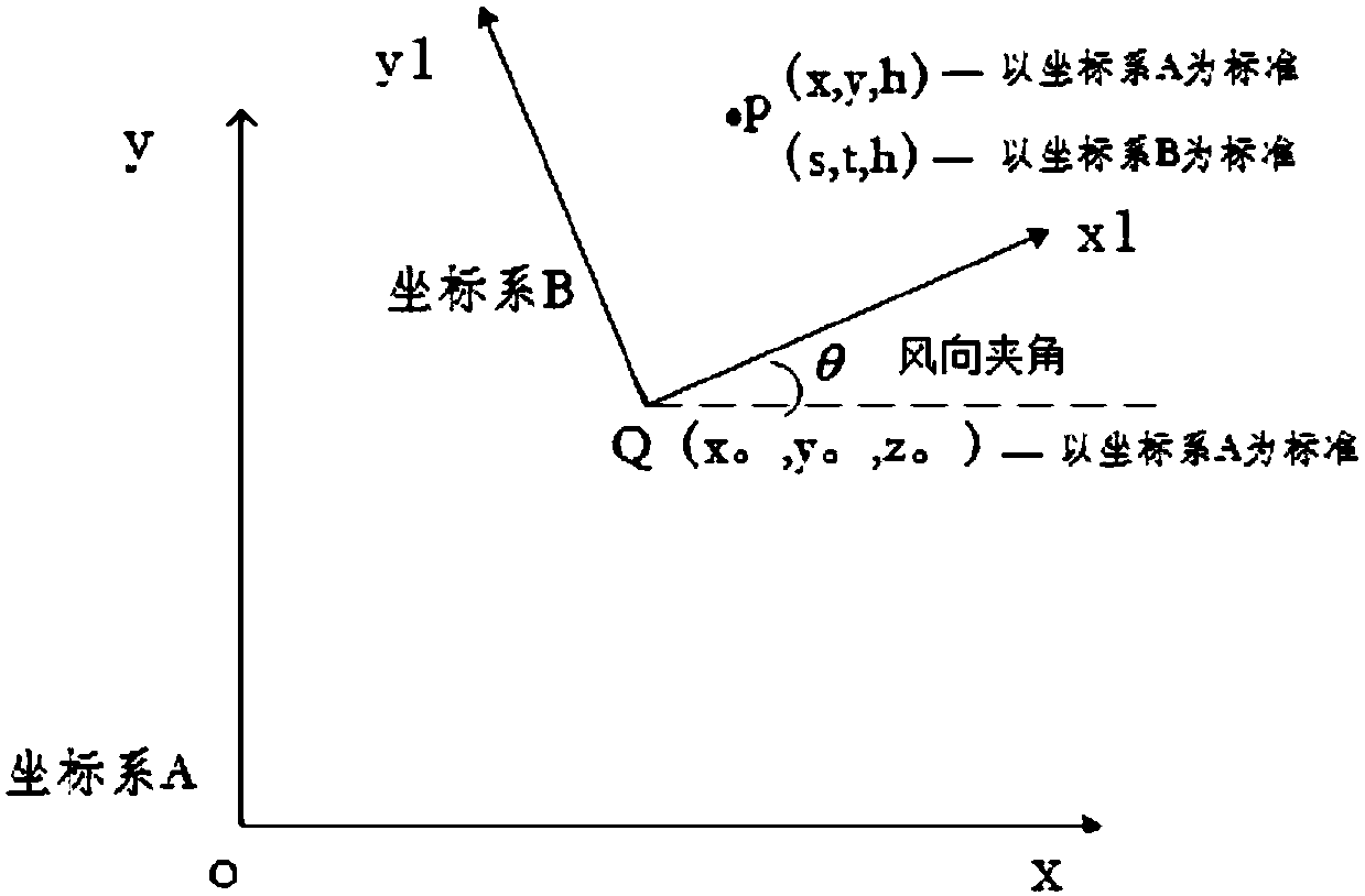
[0041] 2) Establishment of a three-dimensional space coordinate system: based on the vertices of each divided rectangular area of ​​the factory area and the location of the leakage source, establish the right-handed Cartesian coordinate systems A and B respectively, where the coordinate system A is established with the two sides of the rectangular area as the x-axis and the y axis, the z axis is...


PUM


Abstract

The invention discloses a gas leakage source positioning method. The method comprises the following steps: 1, carrying out area division on a monitoring plant, and deploying sensor nodes; 2, establishing a three-dimensional space coordinate system; 3, establishing a gas diffusion model; 3, determining a leakage positioning technology process; 5, establishing a search model; and 6, determining theintensity and the position of a leakage source. Compared with the prior art, the method disclosed in the invention has the advantages of low cost, easiness in deployment, low monitoring area restriction conditions, wide application, high positioning precision and fast positioning speed.

Description

technical field [0001] The invention relates to the field of gas leakage detection, in particular to a method for locating a gas leakage source. Background technique [0002] At present, the problems of controlling air pollution, monitoring the leakage of TVOC gas and regional air quality are becoming more and more prominent, especially in the chemical, steel, coating and other industries. The current leakage source location method mainly adopts the following methods: [0003] 1. Use small robots to search for leakage sources. This method has strong mobility and wide monitoring coverage. However, this method is costly and it is impossible to deploy a wide range of robots in the monitoring area; [0004] 2. Use drones to search and locate the leak area to be tested. This method has high precision, but it requires high cost, poor versatility, and difficult to realize; [0005] 3. Using high-resolution sensors, the monitoring data is sent back to the monitoring center for ana...

Claims


Application Information

Patent Timeline
Patent Type & Authority Applications(China)
IPC IPC(8): G01N33/00G01C21/00G06N3/12
Inventor 张德生全祯业王宏伟
Owner IVOCMN SHANGHAI INTERNET OF THINGS TECH CO LTD
Why Eureka
Try Eureka