
Movable-type calibration method for camera parameters of industrial photogrammetry system

A measurement system and industrial photography technology, applied in the field of calibration, can solve problems such as low accuracy, little calibration information, and deviation of optical coordinates, and achieve the effect of avoiding calibration errors and high calibration accuracy

Inactive Publication Date: 2018-01-19
BEIJING AEROSPACE INST FOR METROLOGY & MEASUREMENT TECH +1
View PDF4 Cites 16 Cited by
  • Summary
  • Abstract
  • Description
  • Claims
  • Application Information

AI Technical Summary

Problems solved by technology

[0003] At present, calibration rods, calibration boards and fixed calibration fields are mainly used for camera parameter calibration. The method is roughly as follows: the calibration method using a flat calibration board or a calibration rod needs to move the calibration board or calibration rod continuously during the calibration process. , this method is relatively convenient and flexible, but the calibration information is less, and only one-dimensional or two-dimensional space constraints are provided, which has certain disadvantages; the calibration method using a fixed calibration field must first establish a calibration field, and calibrate the size of the spatial range according to the needs The main frame is made of steel or carbon fiber materials, and the target points are installed and fixed on the frame. The target points are usually made of reflective materials or LED light sources, and then the target points in the calibration field are assigned by laser trackers and theodolites. As a standard device for camera calibration in industrial photogrammetry systems, the calibration field provides spatial coordinate constraints. However, laser trackers, theodolites and other instruments cannot directly measure the coordinate values ​​of optical targets. The coordinate values ​​calculated by geometric coordinates and the optical coordinates measured by the camera There is a bias, so the accuracy of the method is not high

Method used


Image

  • Movable-type calibration method for camera parameters of industrial photogrammetry system
  • Movable-type calibration method for camera parameters of industrial photogrammetry system
  • Movable-type calibration method for camera parameters of industrial photogrammetry system

Examples


Embodiment Construction

[0026] A mobile calibration method for camera parameters of an industrial photogrammetry system, comprising the following steps:

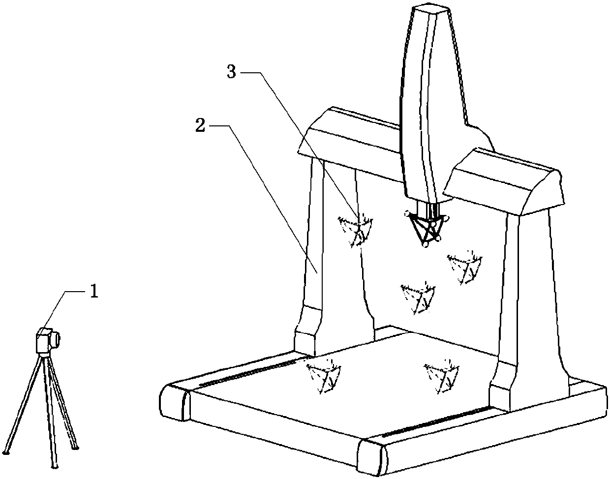
[0027]S1: Select the optical target 3, the optical target 3 must have the optical characteristics that can be recognized by the industrial photogrammetry system 1, such as the use of flat reflective marks, spherical reflective marks, light-emitting LEDs, black and white checkerboard marks, etc. Industrial photogrammetry refers to Two or more images taken from different angles to obtain the three-dimensional geometric information of objects in the scene.

[0028] S2: Construct a three-dimensional motion mechanism, and fix the optical target 3 on the moving part of the three-dimensional motion mechanism, so that the moving part can drive the optical target to perform three-dimensional translational motion. It is fixed on the probe of the three-coordinate measuring machine, and the probe of the three-coordinate measuring machine drives the optical tar...


PUM


Abstract

The invention discloses a movable-type calibration method for camera parameters of an industrial photogrammetry system, and the method comprises the steps: S1, selecting an optical target; S2, constructing a three-dimensional motion mechanism; S3, setting a to-be-calibrated industrial photogrammetry system; S4, recording the image coordinates, collected by the industrial photogrammetry system, ofthe optical center of the optical target; S5, obtaining the coordinate conversion relation between a pixel coordinate system of the industrial photogrammetry system and the world coordinate system through an industrial photogrammetry system imaging model; S6, calculating a calibration error.

Description

technical field [0001] The invention belongs to the field of calibration methods, in particular to a mobile calibration method for camera parameters of an industrial photogrammetry system. Background technique [0002] Industrial photogrammetry refers to the method of obtaining three-dimensional geometric information of objects in the scene based on two or more images taken from different angles. It is simple, reliable, flexible, and widely used. It has been widely used in the field of metrology and testing, and has been widely used in many fields such as industrial monitoring, object recognition, robot self-guidance, aerospace, aviation and military management. Camera parameter calibration is to determine the camera's position, attribute parameters and establish an imaging model, so as to determine the correspondence between the object point in the space coordinate system and its image point on the image plane, which is the basis and premise of photogrammetry work. [0003...

Claims


Application Information

Patent Timeline
Patent Type & Authority Applications(China)
IPC IPC(8): G06T7/80
Inventor 孙增玉刘柯高越刘华袁媛
Owner BEIJING AEROSPACE INST FOR METROLOGY & MEASUREMENT TECH
Learn More