
Novel anesthetic needle device capable of continuous injection for an anesthesiology department

An anesthesia and anesthesia needle technology, which is applied in the field of a new type of continuous injection anesthesia needle device for anesthesia, can solve the problems of poor practicability, troublesome operation, long operation time of anesthesia needle, etc., and achieves the effect of strong practicability and reasonable structure

Inactive Publication Date: 2018-01-23
苏静
View PDF7 Cites 4 Cited by
  • Summary
  • Abstract
  • Description
  • Claims
  • Application Information

AI Technical Summary

Problems solved by technology

[0002] At present, the anesthesia needles used in hospitals can also be called hard waist anesthesia needles, which belong to the traditional structural form that has not changed for many years. The specific operation during anesthesia is more troublesome. The operation time is long, and the anesthesia plane is not easy to adjust
[0003] For example, the patent application publication number CN 202113136 U discloses an anesthetic needle device, which consists of a spinal anesthesia needle, a needle tube body, a needle tube seat, a needle handle and an epidural catheter. The needle tube body is the main part of the present invention, and the whole is hollow. The cylindrical structure of the needle tube body is provided with a needle tube seat at the rear end of the needle tube body, which penetrates into the needle tube body, and a spinal anesthesia needle and an epidural catheter are arranged side by side, and a needle handle is connected to the rear end of the spinal anesthesia needle. simple, less practical

Method used


Image

  • Novel anesthetic needle device capable of continuous injection for an anesthesiology department
  • Novel anesthetic needle device capable of continuous injection for an anesthesiology department

Examples


Embodiment Construction

[0014] The following will clearly and completely describe the technical solutions in the embodiments of the present invention with reference to the accompanying drawings in the embodiments of the present invention. Obviously, the described embodiments are only some, not all, embodiments of the present invention. Based on the embodiments of the present invention, all other embodiments obtained by persons of ordinary skill in the art without making creative efforts belong to the protection scope of the present invention.

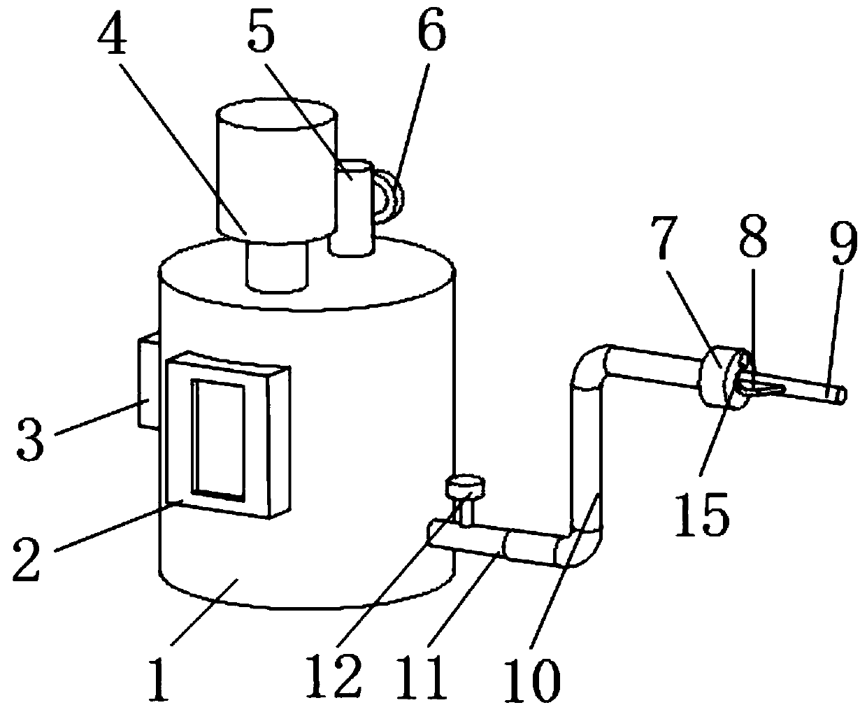
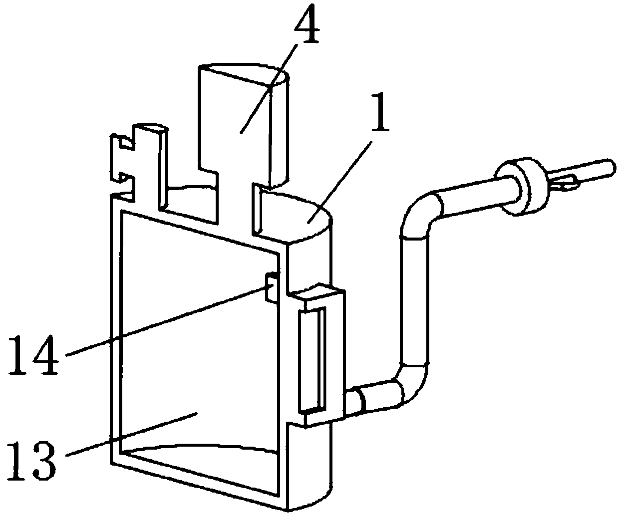
[0015] see Figure 1-2 , the present invention provides a technical solution: a new type of continuous injection anesthesia needle device for anesthesiology department, comprising a casing 1, an inner cavity 13 is arranged in the outer casing 1, a pressure sensor 14 is arranged on the side of the inner cavity 13, and a PLC controller 3 Control the micro pressure pump 4 to inject the anesthesia needle into the patient, feed back the information to the PLC contr...


PUM


Abstract

The invention discloses a novel anesthetic needle device capable of continuous injection for an anesthesiology department. The device comprises a shell, an inner cavity is formed in the shell, a pressure transducer is arranged on the side surface of the inner cavity, a PLC is arranged on the side surface of the shell, a liquid outlet pipe is arranged in the position, close to the bottom surface, of the side surface of the shell, a second electromagnetic valve is arranged on the side surface of the liquid outlet pipe, the end portion of the liquid outlet pipe is provided with a connecting hose,a needle tube base is arranged on the end portion of the connecting hose, and a needle tube is arranged at the center of the side surface of the needle tube base. According to the novel anesthetic needle device capable of continuous injection for the anesthesiology department, the structure is reasonable, the practicability is high, and through a micro pressure pump, the liquid outlet pipe, the inner cavity, the connecting hose and the PLC, continuous injection can be conducted through an anesthetic needle; through the micro pressure pump, the pressure transducer and the PLC, the injection speed of the anesthetic needle is conveniently adjusted; through an observation window, the injection amount of the anesthetic needle and the residual amount in the inner cavity are conveniently observed, and accordingly the device is suitable for application and popularization.

Description

technical field [0001] The invention relates to the technical field of anesthesia appliances, in particular to a novel continuous injection anesthesia needle device for anesthesia. Background technique [0002] At present, the anesthesia needles used in hospitals can also be called hard waist anesthesia needles, which belong to the traditional structural form that has not changed for many years. The specific operation during anesthesia is more troublesome. The operation time is long, and the anesthesia plane is not easy to adjust. [0003] For example, the patent application publication number CN 202113136 U discloses an anesthetic needle device, which consists of a spinal anesthesia needle, a needle tube body, a needle tube seat, a needle handle and an epidural catheter. The needle tube body is the main part of the present invention, and the whole body is hollow The cylindrical structure of the needle tube body is provided with a needle tube seat at the rear end of the nee...

Claims


Application Information

Patent Timeline
IPC IPC(8): A61M19/00
Inventor 苏静冯秀娟刘海霞
Owner 苏静
Learn More