Dust collection device for printing plate roller of printing machine
A technology of dust removal device and printing plate roller, which is applied to printing machines, general parts of printing machinery, printing, etc., can solve the problems of poor quality and low efficiency, and achieve the goal of improving stability, improving flexibility, improving efficiency and quality Effect
- Summary
- Abstract
- Description
- Claims
- Application Information
AI Technical Summary
Problems solved by technology
Method used
Image

Examples
Embodiment 1
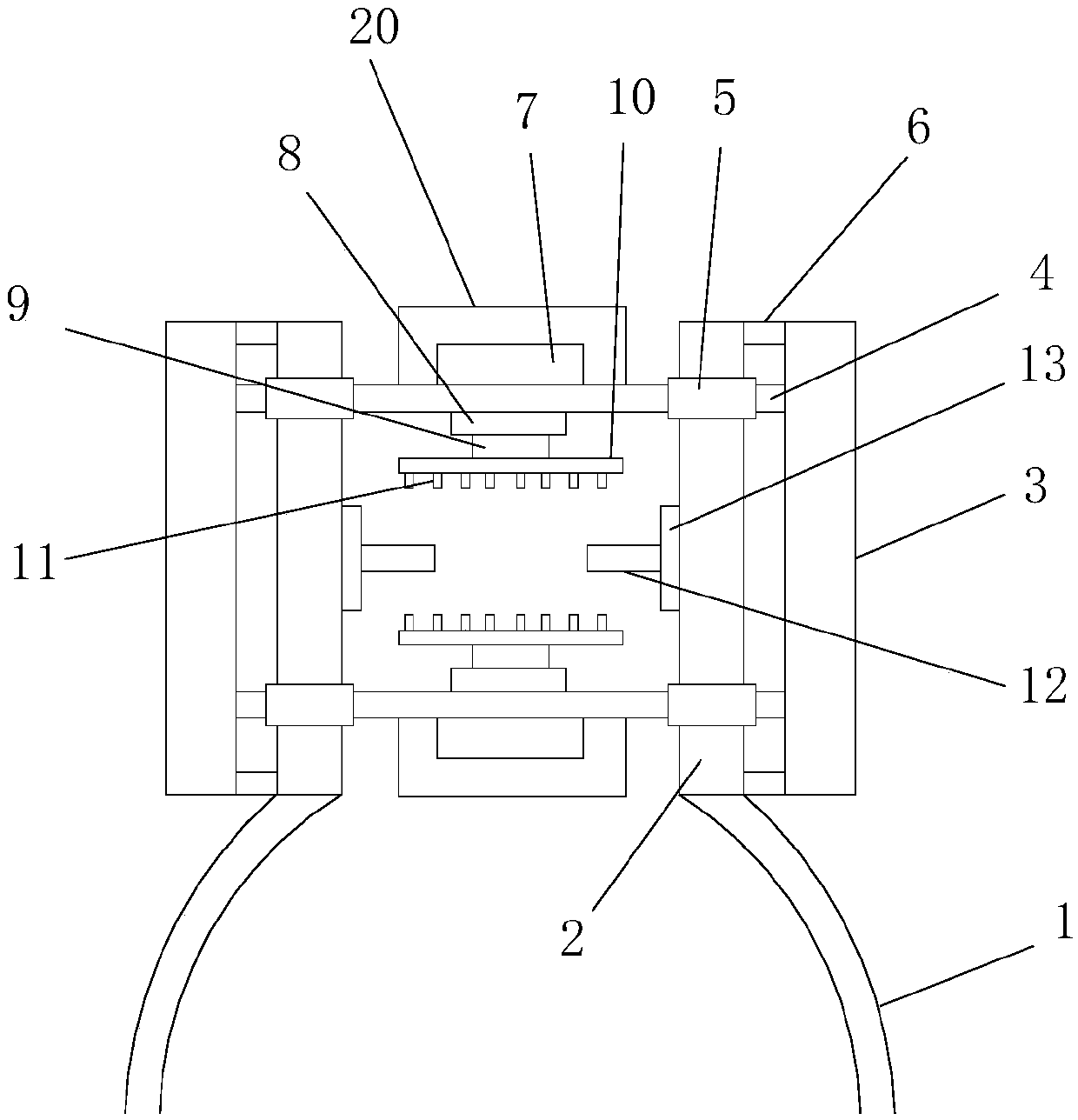
[0025] Such as figure 1 As shown, the present invention provides a dust removal device for a plate cylinder of a printing machine, comprising a bracket 1, a mounting plate 2, a nozzle mounting seat 10, a nozzle 11 and a limit shaft 12, the mounting plate 2 is installed on the bracket 1, and the mounting plate Nozzle mounting seat 10 is installed on 2, nozzle 11 is installed on the nozzle mounting seat 10, limit shaft 12 is installed on one side of the mounting plate, the first motor 3 is installed on one side of the mounting plate 2 through the first motor bracket 6, the second A motor 3 runs through the mounting plate 2 and is provided with a rotating shaft 4. The mounting plate 2 is provided with a rotating shaft installation sleeve 5. The rotating shaft 4 is installed through the rotating shaft mounting sleeve 5. The upper end of the rotating shaft 4 is equipped with a second motor 7 and a blower 20. A first piston 8 is installed on the end of the rotating shaft 4 away from...
Embodiment 2
[0027] The difference between Embodiment 2 of the present invention and Embodiment 1 above is that.
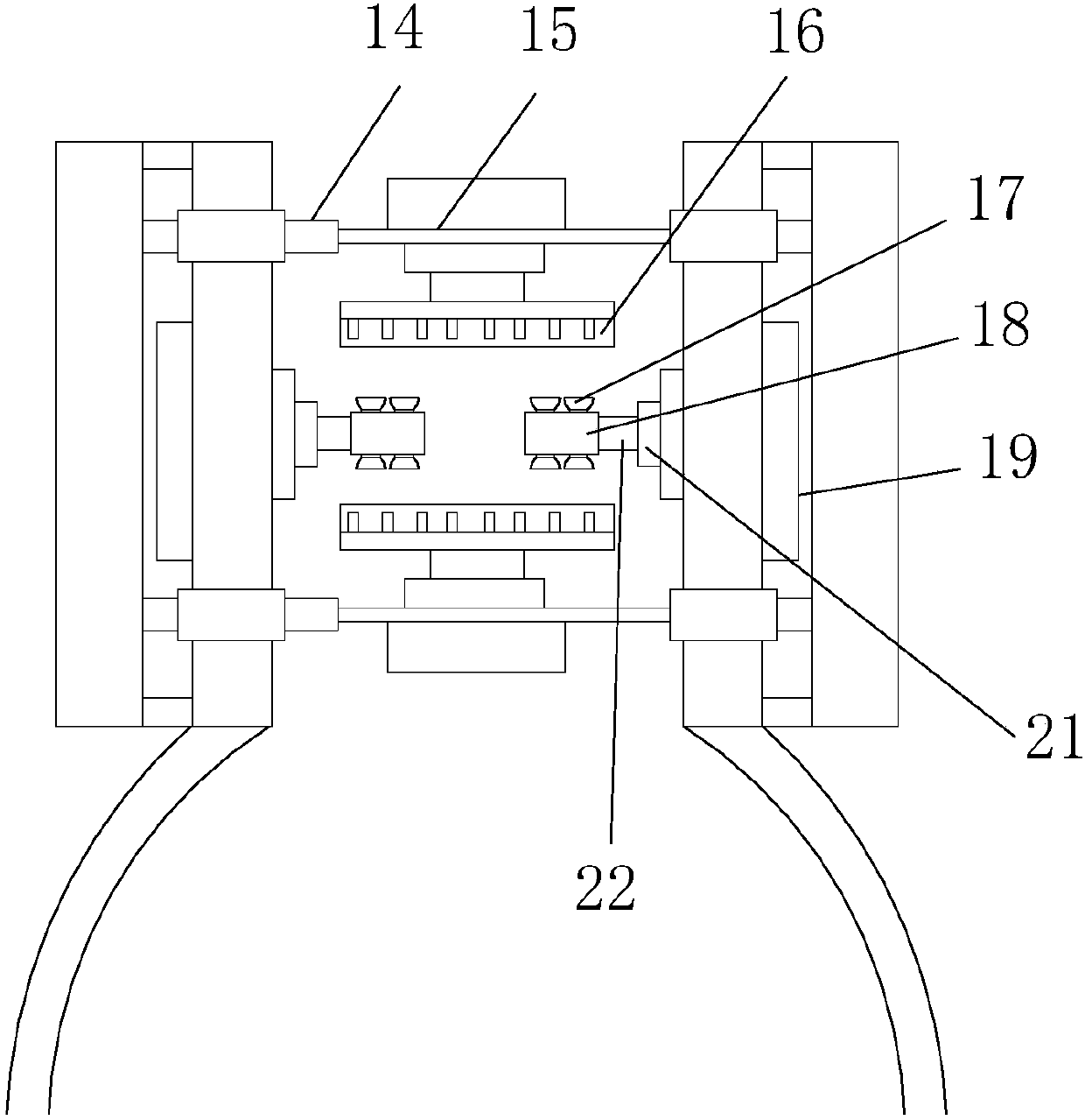
[0028] refer to figure 2 , the rotating shaft 4 is composed of the third piston 14 and the third piston shaft 15, and the second motor 7, the first piston 8 and the blower 20 are all mounted on the third piston shaft 15. By using the third piston shaft 15 to move in the third piston 14, the length of the rotating shaft 4 can be adjusted in the horizontal direction to adapt to printing plate cylinders of different lengths, effectively improving the flexibility of dust removal.
[0029] In the second embodiment, a brush 16 is also installed on the nozzle installation seat 10 . The brush 16 can clean up the dust attached to the printing plate cylinder, which improves the efficiency and quality of dust removal.
[0030] In the second embodiment, the third motor 19 is installed on one side of the mounting plate 2, the fourth piston 21 is installed on the end of the mounting plat...
Embodiment 3
[0033] The difference between Embodiment 3 of the present invention and Embodiment 1 above is that.
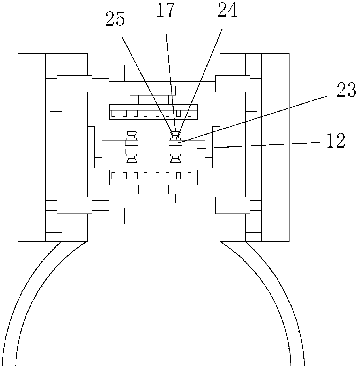
[0034] refer to image 3 , the fourth motor 23 is installed on the limit shaft 12, the fifth piston 24 is installed on the end of the fourth motor 23 away from the limit shaft 12, and the fifth piston shaft 25 is installed on the end of the fifth piston 24 away from the fourth motor 23, A suction cup 17 is installed on the end of the fifth piston shaft 25 away from the fifth piston 24 . Drive the fifth piston shaft 25 to move in the fifth piston 24 through the fourth motor 23, realize the axial adjustment of the suction cup 17 installed on the fifth piston shaft 25 in the limit shaft 12, and realize the inner wall of the printing plate cylinder. The limit is fixed, which improves the stability of fixing the printing plate roller, and further improves the efficiency and quality of dust removal.
PUM
 Abstract
Description
Claims
Application Information
 - R&D
- Intellectual Property
- Life Sciences
- Materials
- Tech Scout
- Unparalleled Data Quality
- Higher Quality Content
- 60% Fewer Hallucinations
Browse by: Latest US Patents, China's latest patents, Technical Efficacy Thesaurus, Application Domain, Technology Topic, Popular Technical Reports.
© 2025 PatSnap. All rights reserved.Legal|Privacy policy|Modern Slavery Act Transparency Statement|Sitemap|About US| Contact US: help@patsnap.com