Using method for adjustable wire winding and unwinding frame

An adjustable, retractable and unwinding technology, applied in the field of machinery and equipment, can solve the problems affecting the smooth progress of production or engineering, waste of space in the reel workshop, tensile damage, etc., and achieve the effect of increasing the scope of use, saving space, and increasing the load

Inactive Publication Date: 2018-01-23
WUHU MINTAI COPPER IND
View PDF8 Cites 1 Cited by
  • Summary
  • Abstract
  • Description
  • Claims
  • Application Information

AI Technical Summary

Problems solved by technology

Existing yarns, threads, ribbons, ropes, and cables are usually made into packages with mandrels or pancake-shaped packages without mandrels. In the process, if the pulling direction is too high, the yarn, thread, tape, rope, and cable wound on the pay-off frame will be off-line, resulting in poor unwinding and mutual entanglement. At this time, the machine must be stopped and the Scattered yarns, threads, belts, ropes, and cables are rewound, seriously affecting the smooth progress of production or engineering
And in the prior art, the pay-off stand completely relies on the external force to pull the wire to realize the release during the pay-off process, so it will have a certain stretching damage effect on the yarn, thread, belt, rope, and cable, and serious damage to the wire will occur. The phenomenon that the material is pulled off, and the existing pay-off rack is constant for the one-time pay-off amount carried by it. If the wire reel is large, it is necessary to replace a larger pay-off rack, which is troublesome. If the wire reel is larger Small, then there will be a waste of wire reels and workshop space

Method used


Image

  • Using method for adjustable wire winding and unwinding frame
  • Using method for adjustable wire winding and unwinding frame

Examples


Embodiment 1

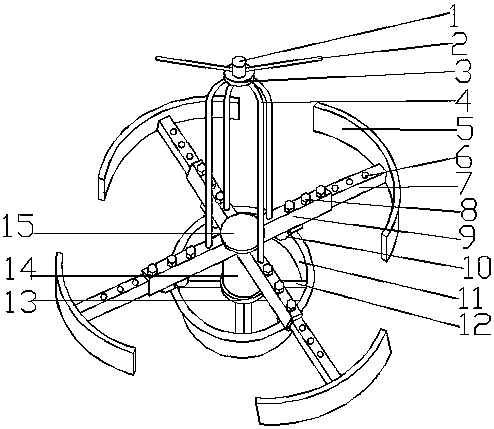
[0022] An adjustable take-up and pay-off rack, such as figure 1 As shown, it includes a fixed part and a rotating part. The fixed part includes a first base 13, a fixed ring 11 and a first connecting rod 12, and the first connecting rod 12 is respectively fixed to the first base 13 and the fixed ring 11. The connection ensures the stability of the pay-off frame during the pay-off process. The rotating part includes a second base 15, a motor 14, a second connecting rod 9, a protective ring 5, a sleeve rod 7, a rotating frame 4, a fixed seat 3, a guide seat 1 and a guide rod 2, and the motor 14 is positive and negative Rotating motor can realize the two operating processes of the present invention, wire take-up and pay-off, and improve its utilization value; and it is located on the upper end of the first base 13, and is fixedly connected with the second base 15, and the motor 14 acts as a motor. Drive the second base 15, control the rotation and stop of the rotating part, real...

Embodiment 2

[0026] Same as embodiment 1, the difference is that there are 3 guide rods 2, 5 first connecting rods 12 and 5 second connecting rods 9, which can ensure the load of the rotating part and more effectively prevent falling off. line occurrences.

Embodiment 3

[0028] Same as embodiment 1, the difference is that there are 4 guide rods 2, 6 first connecting rods 12 and 6 second connecting rods 9, which can greatly increase the load of the rotating part and expand its application range. And more effectively prevent the occurrence of off-line and winding phenomenon.


PUM


Abstract

The invention discloses a using method for an adjustable wire winding and unwinding frame and belongs to the field of mechanical equipment. The adjustable wire winding and unwinding frame comprises afixed part and a rotating part. The fixed part comprises a first base, a fixed ring and a first connecting rod. The rotating part comprises a second base, a motor, second connecting rods, protective rings, sleeve rods, a rotating frame, a fixed seat, a guide seat and guide rods. In use, the lengths of the portions, protruding out of the second connecting rods, of the sleeve rods are well adjustedfirstly according to the need; then the guide rods are screwed down, a wire material is put into the adjustable wire winding and unwinding frame, and then the guide rods are screwed into the guide seat and tightened; and after one end of the wire material is well connected with a downstream machine, the motor is started, and it is guaranteed that the rotating speed of the motor is equal to the pulling-in speed of the downstream machine. Wire-off and twining in unwinding can be avoided, active wire unwinding and winding are achieved, the bearing capacity of one-time wire unwinding can be adjusted, and by arranging rollers, the load capacity is improved, so that the adjustable wire winding and unwinding frame is made to be suitable for wire coils of different sizes and materials.

Description

[0001] The patent application of the present invention is a divisional application with the application number: 2014106321824, the filing date of the original application is: 2014-11-12, and the name of the invention is: an adjustable take-up and release rack. technical field [0002] The invention belongs to the field of mechanical equipment, and more specifically relates to a method for using an adjustable take-up and pay-off wire rack. Background technique [0003] In various engineering technologies, flexible yarns, threads, tapes, ropes, and cables with lengths are commonly used. In order to reduce volume and facilitate transportation and storage, production units usually wind these yarns, threads, tapes, ropes, and cables into For large packages of different specifications, when the user uses these packaged products, they will be unwound from the package at the construction site. If effective control cannot be carried out during the unwinding process, flexible yarns and...

Claims


Application Information

Patent Timeline
Patent Type & Authority Applications(China)
IPC IPC(8): B65H75/38B65H75/44B65H75/48
Inventor 颜承龙
Owner WUHU MINTAI COPPER IND
Why Eureka
Try Eureka