Adjustable pay-off stand

An adjustable pay-off rack technology, which is used in the delivery of filamentous materials, thin material handling, transportation and packaging, etc., can solve problems that affect the smooth progress of production or engineering, waste of space in the reel workshop, and tensile damage. Achieve the effect of simple structure, save space and avoid stretching damage

Inactive Publication Date: 2015-03-11
WUHU MINTAI COPPER IND
View PDF8 Cites 0 Cited by
  • Summary
  • Abstract
  • Description
  • Claims
  • Application Information

AI Technical Summary

Problems solved by technology

Existing yarns, threads, ribbons, ropes, and cables are usually made into packages with mandrels or pancake-shaped packages without mandrels. In the process, if the pulling direction is too high, the yarn, thread, tape, rope, and cable wound on the pay-off frame will be off-line, resulting in poor unwinding and mutual entanglement. At this time, the machine must be stopped and the Scattered yarns, threads, belts, ropes, and cables are rewound, seriously affecting the smooth progress of production or engineering
And in the prior art, the pay-off stand completely relies on the external force to pull the wire to realize the release during the pay-off process, so it will have a certain stretching damage effect on the yarn, thread, belt, rope, and cable, and serious damage to the wire will occur. The phenomenon that the material is pulled off, and the existing pay-off rack is constant for the one-time pay-off amount carried by it. If the wire reel is large, it is necessary to replace a larger pay-off rack, which is troublesome. If the wire reel is larger Small, then there will be a waste of wire reels and workshop space

Method used


Image

  • Adjustable pay-off stand

Examples


Embodiment 1

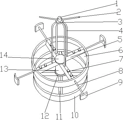
[0020] In addition, the swivel frame 4 is located between 1 / 3 and 1 / 4 of the upper end surface of the second connecting rod 5 from the side of the second base 14, which ensures that the present invention can be placed to a greater extent. More wires also ensure the pay-off effect. There are 2 guide rods 2, 4 first connecting rods 11 and 4 second connecting rods 5, and at least 2 screws 7 are arranged in the screw holes on the second connecting rod 5, so that The increase of the stress point of the strut 8 and the increase of the force range greatly increase the stability of the strut 8 in the through hole provided on the second connecting rod 5, and can improve the stability of the strut 8. 8 load, not easy to deform. The guard plate 9 is an arc-shaped plate, its inner diameter is equal to the outer diameter of the protective ring 6, and its upper end surface is 5-10 cm higher than the pole 8 fixed in the middle, and the guard plate 9 effectively avoids The wire material br...

Embodiment 2

[0024] Example 3

Embodiment 3

[0026] The above schematically describes the present invention and its implementation, which is not restrictive, and what is shown in the drawings is only one of the implementations of the present invention, and the actual structure is not limited thereto. Therefore, if a person of ordinary skill in the art is inspired by it, without departing from the inventive concept of the present invention, without creatively designing a structural mode and embodiment similar to the technical solution, it shall all belong to the protection scope of the present invention .


PUM


Abstract

The invention discloses an adjustable pay-off stand, which belongs to the field of mechanical equipment. The adjustable pay-off stand comprises a fixed part and a rotating part, the fixed part comprises a first base, a fixed ring and first connecting rods, the rotating part comprises a second base, a motor, second connecting rods, a guard ring, a rotating stand, a fixed base, a guide base and two to four guide rods, the motor is arranged on the upper end of the first base, and is fixedly connected with the second base, the fixed joints between the second connecting rods and the guard ring are provided with like through holes, support rods which are matched with the through holes are arranged in the through holes, two to four screw holes are equidistantly arranged in each second connecting rod, screws are arranged in the screw holes, the screw holes communicate with the through holes, guard plates are fixed at the other ends of the support rods, the guide rods are equidistantly arranged on the guide base and connected with the guide base through screw threads, and the guide rods make the included angle of 10 to 30 degrees with a horizontal line. The adjustable pay-off stand can prevent the occurrence of dropping during paying-off, and realizes active paying-off, moreover, entanglement cannot take place, and the bearing capability for one-time paying-off can be adjusted, so that the adjustable pay-off stand is applicable to coils of different sizes.

Description

technical field [0001] The invention belongs to the field of mechanical equipment, and more specifically relates to an adjustable pay-off frame. Background technique [0002] In various engineering technologies, flexible yarns, threads, tapes, ropes, and cables with lengths are commonly used. In order to reduce volume and facilitate transportation and storage, production units usually wind these yarns, threads, tapes, ropes, and cables into For large packages of different specifications, when the user uses these packaged products, they will be unwound from the package at the construction site. If effective control cannot be carried out during the unwinding process, flexible yarns and threads will The unwinding of belts, ropes and cables is not smooth and entangled with each other, which not only wastes materials, but also affects the smooth progress of application projects. In order to solve these problems, people usually put large packages of yarn, thread, tape, rope, and ...

Claims


Application Information

Patent Timeline
Patent Type & Authority Applications(China)
IPC IPC(8): B65H49/32
Inventor 颜承龙
Owner WUHU MINTAI COPPER IND
Why Eureka
Try Eureka