Fuse for detecting failure of gas trap

A fuse and air trap technology, applied in the field of existing devices, can solve the problems of complex and expensive gas sensors

Pending Publication Date: 2017-02-15
BL TECH INC
View PDF8 Cites 0 Cited by
  • Summary
  • Abstract
  • Description
  • Claims
  • Application Information

AI Technical Summary

Problems solved by technology

Typical commercially available gas sensors for measuri

Method used


Image

  • Fuse for detecting failure of gas trap
  • Fuse for detecting failure of gas trap
  • Fuse for detecting failure of gas trap

Examples


Embodiment Construction

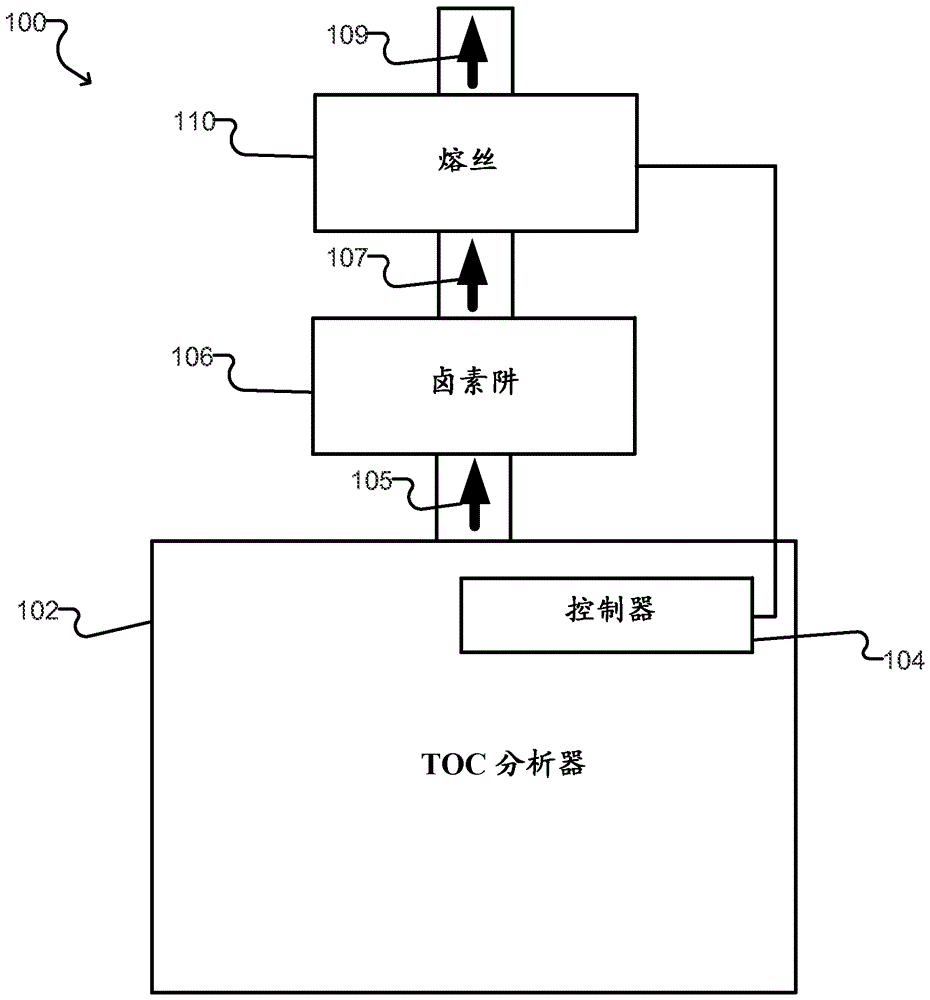
[0016] figure 1 An example system 100 is shown that includes a gas detection fuse 110 according to one embodiment. The system 100 includes a TOC analyzer 102, which may be any suitable sample analyzer as known in the art. TOC analyzer 102 generates exhaust gases 105 as it analyzes a sample, and these exhaust gases are directed to halogen trap 106 . The halogen trap 106 may, for example, comprise a bed of activated carbon. The halogen trap 106 typically absorbs the halogen gas so that the gas 107 exiting the trap 106 is substantially free of halogen. However, once trap 106 is saturated, or if trap 106 fails, gas 107 may contain chlorine or other halogen gas. After passing through trap 106 , gas 107 contacts gas detection fuse 110 and is then exhausted through outlet 109 to the surrounding environment.

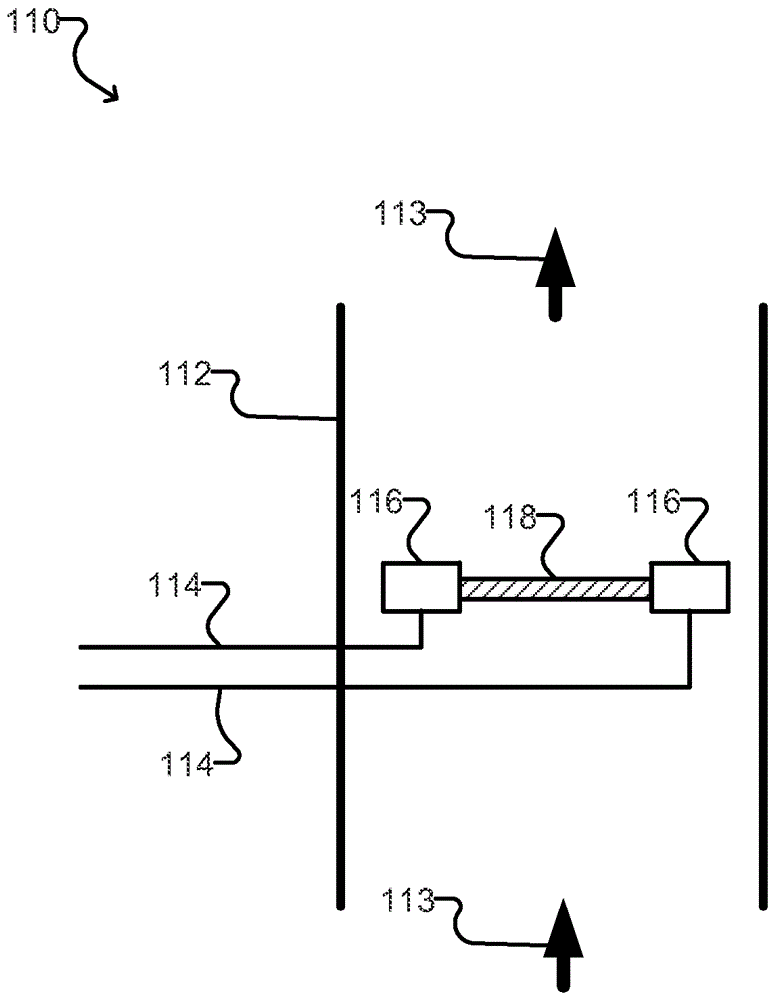
[0017] As described further below, the fuse 110 includes a connection member of a conductive material connected between two electrodes. The conductive material is selected ...


PUM

PropertyMeasurementUnit
Thicknessaaaaaaaaaa

Abstract

A gas detection fuse comprising a thin strip or sheet of a conductive material, such as a metal, connecting two electrodes for detecting a gas of interest. The metal is selected to be reactive with the gas of interest, and has a relatively large surface area, such that when the gas of interest contacts the metal, the electrical connection between the electrodes is broken (e.g., due to the metal losing physical integrity, or becoming non-conductive, as a result of the reaction with the gas). The gas of interest may be chlorine, and the conducting material may be tin. When the tin is exposed to chlorine the tin becomes oxidized to produce liquid tin tetrachloride, thus breaking the electrical connection.

Description

technical field [0001] The present disclosure generally relates to detection of hazardous gases. More particularly, the present disclosure relates to devices for detecting the presence of chlorine gas escaping a halogen trap. Background technique [0002] Sample analyzers such as Total Organic Carbon (TOC) analyzers can sometimes produce hazardous gases, depending on the sample being analyzed. In particular, chlorine gas generated when analyzing samples containing chlorides is highly corrosive and can potentially cause personal injury and equipment failure in the field. Some TOC analyzers, including the InnovOx™ TOC Analyzer from GE Analytical Instruments, include halogen traps. For example, activated carbon in a halogen trap can absorb between 20% and 50% of its mass in chlorine (P. Lodewyckx and L. Verhoeven, Using the Modified Wheeler-Jonas Equation to Describe the Absorption of Inorganic Molecular Chlorine, 2003 1 25, pp. 1217-1219). However, once the reactive sites ...

Claims


Application Information

Patent Timeline
IPC IPC(8): G01N27/12G01N33/00G01N31/00G01N33/18
CPCG01N27/12G01N33/0052G01N33/1846G01N31/005G01N27/125
Inventor J.C.曼利
Owner BL TECH INC
Why Eureka
Try Eureka