Pay-off stand

A technology of pay-off rack and revolving rack, applied in the field of pay-off rack, can solve the problems affecting the smooth progress of production or engineering, tensile damage, unsmooth unwinding, etc., to achieve simple structure, avoid tensile damage, and easy to manufacture. Effect

Inactive Publication Date: 2015-04-08
WUHU MINTAI COPPER IND
View PDF7 Cites 0 Cited by
  • Summary
  • Abstract
  • Description
  • Claims
  • Application Information

AI Technical Summary

Problems solved by technology

Existing yarns, threads, ribbons, ropes, and cables are usually made into packages with mandrels or pancake-shaped packages without mandrels. In the process, if the pulling direction is too high, the yarn, thread, tape, rope, and cable wound on the pay-off frame will be off-line, resulting in poor unwinding and mutual entanglement. At this time, the machine must be stopped and the Scattered yarns, threads, belts, ropes,

Method used


Image

  • Pay-off stand

Examples


Embodiment 1

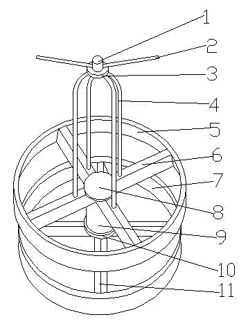
[0018] Such as figure 1 As shown, a pay-off rack includes a fixed part and a rotating part. The fixed part includes a first base 10, a fixed ring 7 and a first connecting rod 11, and the first connecting rod 11 is respectively connected to the first base 10 and the fixing ring 7 are fixedly connected to ensure the stability of the pay-off rack during the pay-off process. The rotating part includes a second base 8, a motor 9, a second connecting rod 6, a guard ring 5, a rotating frame 4, a fixing base 3, a guide base 1 and a guide rod 2, and the motor 9 is arranged on the first base The upper end of 10 is fixedly connected to the second base 8. The motor 9 drives the second base 8 to control the rotation and stop of the rotating part to realize the active pay-off, which greatly avoids the misalignment during the pay-off process. The tensile damage of the wire prevents the phenomenon of wire being broken; the second connecting rod 6 is fixedly connected with the second base 8 an...

Embodiment 2

[0022] Same as embodiment 1, the difference is that there are 3 guide rods 2, and the first connecting rod 11 and the second connecting rod 6 are both 5, which can ensure the load of the rotating part and prevent it from falling off more effectively. The occurrence of the line situation.

Embodiment 3

[0024] Same as embodiment 1, the difference is that there are 4 guide rods 2, and the first connecting rod 11 and the second connecting rod 6 are both 6, which can greatly increase the load of the rotating part and expand its use range. And more effectively prevent the occurrence of disconnection and winding phenomenon.


PUM


Abstract

The invention discloses a pay-off stand and belongs to the field of mechanical equipment. The pay-off stand comprises a fixed portion and a rotating portion, the fixed portion comprises a first base, a fixing ring and a first connecting rod, the first connecting rod is fixedly connected with the first base and the fixing ring respectively, the rotating portion comprises a second base, a motor, a second connecting rod, a protecting ring, a rotating frame, a fixing seat, a guide seat and 2-4 guide rods, the motor is arranged at the upper end of the first base and fixedly connected with the second base, the guide rods are equidistantly arranged on the guide seat and are in threaded connection with the same, and each guide rod and the horizontal line forms an included angle of 10-30 degrees. Off-line circumstance in the process when the pay-off stand pays off can be avoided, the pay-off stand is smooth in unwinding and free of mutual winding and realizes active paying off, tension damage to wires in the process of paying off is avoided, and the phenomenon that the wires are broken by tensioning is eliminated. The pay-off stand has the advantages of simple structure, reasonable design and easiness in manufacturing.

Description

technical field [0001] The invention belongs to the field of mechanical equipment, and more specifically relates to a pay-off frame. Background technique [0002] In various engineering technologies, flexible yarns, threads, tapes, ropes, and cables with lengths are commonly used. In order to reduce volume and facilitate transportation and storage, production units usually wind these yarns, threads, tapes, ropes, and cables into For large packages of different specifications, when the user uses these packaged products, they will be unwound from the package at the construction site. If effective control cannot be carried out during the unwinding process, flexible yarns and threads will The unwinding of belts, ropes and cables is not smooth and entangled with each other, which not only wastes materials, but also affects the smooth progress of application projects. In order to solve these problems, people usually put large packages of yarn, thread, tape, rope, and cable into t...

Claims


Application Information

Patent Timeline
IPC IPC(8): B65H49/28
Inventor 颜承龙
Owner WUHU MINTAI COPPER IND
Why Eureka
Try Eureka