[0024] The technical solution will be described in detail below through a preferred embodiment in conjunction with the drawings.
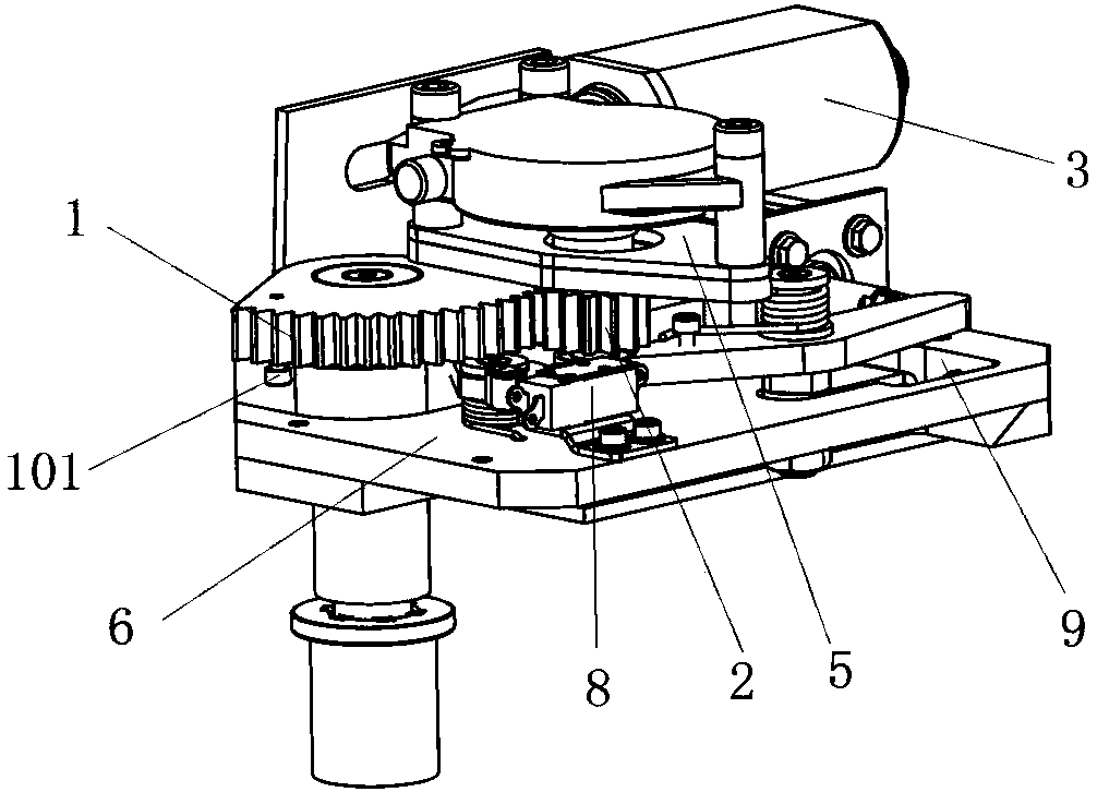
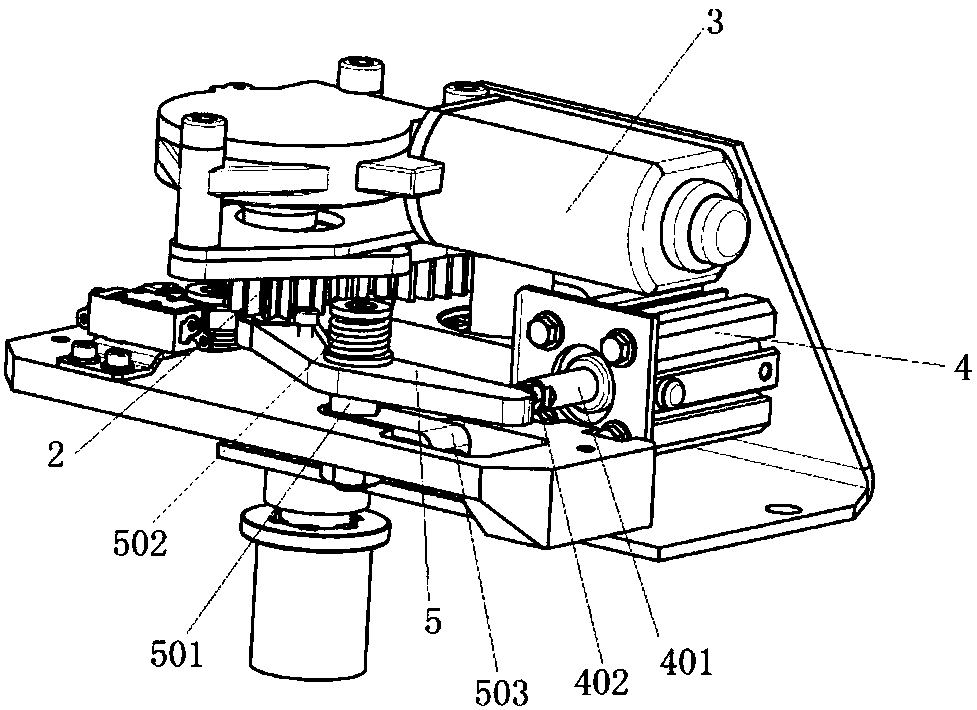
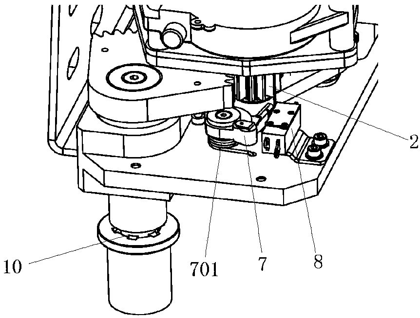
[0025] Such as Figure 1-3 As shown, an electric double-opening inner swing door includes a door shaft 11, a door leaf 12 that rotates with the door shaft 11, and two driving devices that drive the door shaft 11 to rotate. The driving device is used to drive the inner swing door to open/close the door, including Door controller, sector gear coaxially driven with the door shaft 11 of the internal swing door 1, a driving mechanism for driving the sector gear 1 to rotate, and an unlocking mechanism for disengaging the drive mechanism from the sector gear 1, sector gear 1 , The driving mechanism and the unlocking mechanism are both installed on the mounting plate 6, and the sector gear 1 and the door shaft 11 of the swing door are connected by a spline shaft 10.
[0026] The driving mechanism includes a motor gear 2 and a motor 3 that drives the motor gear 2 to rotate. The unlocking mechanism includes a cylinder 4, a cylinder push rod 401 extending from the cylinder 4, and a lock 5 at the end of the cylinder push rod 401. The end of its contact with the lock gear 5 is provided with an adjustment screw 402 for adjusting the degree of meshing between the motor gear 2 and the sector gear 1; the end of the lock gear 5 is drivingly connected with the axle of the motor gear 2, as shown in the figure, the motor gear The force point of 2 is close to the rotation center of gear 5, using the principle that the connecting rod passes the dead center, and the structure close to the "dead point" enables a smaller cylinder 4 to achieve a larger locking force, and gear 5 can be locked around The gear shaft 501 rotates. One end of the two gear lock 5 arms forming an obtuse angle at the gear lock shaft 501 is in contact with the cylinder push rod 401, and the other end is driven by the motor gear 2. This end is the "end".
[0027] In this embodiment, a motor gear bearing is provided on the axle of the motor gear 2, and the motor gear bearing is fixedly connected to the end of the lock 5;
[0028] The lock gear 5 is provided with a lock gear shaft 501 for horizontal rotation around it, and the lock gear shaft 501 is provided with an elastic element for applying torsion and resilience to the lock gear 5. The elastic element in this embodiment is a torsion spring 502, so The torsion spring 502 is sleeved on the outer wall of the lock shaft 501; when the cylinder 4 is unlocked, the cylinder push rod 401 pushes the lock 5 to rotate, causing the motor gear 2 to mesh with the sector gear 1 and twist the elastic element. When the cylinder 4 is unlocked When it is in air, the lock gear 5 rotates under the torsional resilience of the elastic element and drives the motor gear 2 to separate from the sector gear 1. The mounting plate 6 is provided with a groove 9, the bottom of the locking shaft 501 is connected with a locking plate 503, and the end of the locking plate 503 is fixedly installed in the groove 9 by a set screw.
[0029] The mounting plate 6 is also provided with a trigger plate 7, and the sector gear 1 is provided with a stop pin 101, and the stop pin 101 contacts the trigger plate 7; when the door is closed, the stop pin 101 rotates with the sector gear 1 and pushes the trigger plate when the door is closed in place 7 Trigger close end switch 8, close end switch 8 sends a close end signal to the door controller; trigger plate 7 includes a cam and cam reset torsion spring 701 installed on the cam axle, stop pin 101 pushes trigger plate 7 to trigger close position When the switch 8 is switched, the cam reset torsion spring 701 is twisted; when the door is opened, the stop pin 101 rotates with the sector gear 1, and the cam reset torsion spring 701 drives the cam to rotate to the initial position.
[0030] The motor 3 in this embodiment is a DC worm gear motor 3, and the motor 3 is connected with a motor 3 Hall switch. The motor 3 Hall switch detects the position of the motor 3 and transmits the position signal to the gate controller in real time; The controller also monitors the current change of the motor 3. The door controller judges whether the door leaf 12 is blocked during the opening and closing process according to the position signal and current change of the motor 3, and controls the driving device to drive the door leaf 12 to change the movement state when the obstacle is encountered. If an obstacle is encountered during the opening and closing process, the current of the motor 3 and the position of the Hall will change, and the anti-pinch operation can be realized by the controller, which improves the safety and is responsive.
[0031] In addition, the door leaf 12 is also equipped with handrails to facilitate passengers to get on and off. In addition, a micro switch is installed at the position where the inner swing door is opened. The micro switch is connected with the door controller, and the door controller judges whether the door is opened according to the current signal and the micro switch signal.
[0032] The overall schematic diagram of the present invention is as Figure 4 , 5 As shown, the working principle when opening/closing/emergency unlocking is:
[0033] 1. Electric closing:
[0034] When the door is in the open state, the cylinder 4 takes in air, and the cylinder push rod 401 pushes the lock 5 to rotate, thereby pushing the motor gear 2 to the sector gear 1 to mesh the two gears. By adjusting the adjusting screw 402 on the cylinder push rod 401, the gear meshing gap can be adjusted so that the gears can mesh well;
[0035] The driving motor 3 rotates forward, driving the motor gear 2 to drive the sector gear 1 to rotate;
[0036] The sector gear 1 drives the door shaft 11 connected with the spline shaft 10 to rotate to realize electric door closing;
[0037] The stop pin 101 on the sector gear 1 pushes the trigger plate 7 to trigger the switch assembly, the switch assembly outputs a signal to the door controller, and the door controller completes the door closing action.
[0038] 2. Electric door opening:
[0039] When the door is in the closed state, the cylinder 4 takes in air, and the cylinder push rod 401 pushes the lock gear 5 to rotate, thereby pushing the motor gear 2 to the sector gear 1 to mesh the two gears. By adjusting the adjusting screw 402 on the cylinder push rod 401, the gear meshing gap can be adjusted so that the gears can mesh well;
[0040] The drive motor 3 is reversed to drive the motor gear 2 to drive the sector gear 1 to rotate;
[0041] The sector gear 1 drives the door shaft 11 connected to it through the spline shaft 10 to rotate to realize electric door opening.
[0042] 3. Manual closing:
[0043] When the door is in the open state, the cylinder 4 is exhausted, the lock 5 is reset under the action of the lock 5 reset torsion spring 701 and the cylinder push rod 401 is retracted, and the motor gear 2 is separated from the sector gear 1;
[0044] Manually close the door in place;
[0045] The cylinder 4 takes in air, so that the motor gear 2 meshes with the sector gear 1 to achieve locking.
[0046] 4. Emergency unlock to open the door manually:
[0047] When the door is closed, operate the emergency unlocking device to exhaust the cylinder 4, and the lock 5 is reset under the action of the lock 5 reset torsion spring 701 and the cylinder push rod 401 is retracted, so that the motor gear 2 and the sector gear 1 are separated ;
[0048] Complete the door opening manually.
[0049] 5. Full locking: at any position, cylinder 4 air intake, motor gear 2 meshes with sector gear 1, through the self-locking function of worm gear motor 3, it can be locked at any position.
[0050] In addition, such as Image 6 Shown are the left and right finger guard strips of the present invention. The figure is a top view of the symmetrical left finger guard strip and the right finger guard strip. The left finger guard strip and the right finger guard strip The strips are respectively connected to the two door leaves 12, and each finger guard strip includes a main body portion 131. One end of the main body portion 131 of the left finger guard strip, which is the upper end in the figure, extends an outer sealing lip 132 toward the door seam. The other end of the portion 131, that is, the lower end in the figure, extends a sealed corner portion 133 toward the door gap. Both ends of the main body 131 extend out of the door panel lip 138 toward the door panel, and cover the glass bonding surface of the door panel.
[0051] The end of the sealing corner 133 is bent inward and extends an inner sealing lip 134. The outer sealing lip 132 and the sealing corner 133 are both connected to the main body 131 through a connecting bone, which is connected to the outer sealing lip 132 A cavity is enclosed between the main body portion 131 and the connecting bone and the sealing corner portion 133 and the main body portion 131 are also enclosed.
[0052] The connecting bones include a main connecting bone 135 connected to the main body portion 131, an outer connecting bone 136 extending from the autonomous connecting bone 135, and a corner connecting bone 137. The outer connecting bone 136 is connected to the outer sealing lip 132, and the corner connecting bone 137 is connected On the sealed corner 133.
[0053] The main body part 131 is provided with a through hole in the center, and the main body part 131 is provided with a connection part for assembling with the door panel at the contact position with the door panel.
[0054] When the double-opening inner swing door is closed, the outer sealing lip 132 of the left finger guard rubber strip is adjacent to the sealing corner 133 of the right finger guard rubber strip, and the outer sealing lip 132 of the right finger guard rubber strip is adjacent to the left finger guard rubber strip. The sealing corners 133 are adjacent, the inner sealing lip 134 of the left finger guard rubber strip is adjacent to the inner sealing lip 134 of the right finger guard rubber strip. In this embodiment, the outer sealing lip 2 of the left finger guard rubber strip is adjacent to the right The sealing corner 133 of the finger guard rubber strip has an interference fit, the outer sealing lip 132 of the right finger guard rubber strip is in interference fit with the sealing corner 133 of the left finger guard rubber strip, and the inner sealing lip of the left finger guard rubber strip 134 Interference fit with the inner sealing lip 134 of the right finger guard strip to achieve a better sealing effect.
[0055] The combined structure of the left finger guard rubber strip and the right finger guard rubber strip has a total width of less than 90mm. If there is an obstacle when the door system is closed, the cavity of the finger guard will be compressed. Because the space between the left and right finger guard cavities is smaller, smaller obstacle detection can be achieved. The minimum obstacle detection width is 10mm; smaller After the obstacle is clamped, the cavity is compressed, which can avoid clamping injuries and can easily extract the obstacle.
[0056] The above are only the preferred embodiments of the present invention. It should be pointed out that for those of ordinary skill in the art, without departing from the principle of the present invention, several improvements and modifications can be made, and these improvements and modifications should also be considered This is the protection scope of the present invention.