A plunger cylinder for pumping water

A plunger cylinder and plunger technology, which is applied in the field of pressurized water pumps, can solve the problems of high cost, high power consumption, and environmental protection, and achieve the effects of low cost, avoiding the use of electric energy, and saving energy

Active Publication Date: 2019-01-04
东营市虹田石油装备有限公司
View PDF5 Cites 0 Cited by
  • Summary
  • Abstract
  • Description
  • Claims
  • Application Information

AI Technical Summary

Problems solved by technology

[0002] The existing water pump provides the power source through the motor, and the motor drives the water-pressing mechanism inside the pump. The water-pressing mechanism quickly and briefly pushes the water in the pump to move forward to realize the pumping of the pump. For high-lift pumping, this method consumes power Big, expensive, and not environmentally friendly

Method used


Image

  • A plunger cylinder for pumping water
  • A plunger cylinder for pumping water
  • A plunger cylinder for pumping water

Examples


Embodiment 1

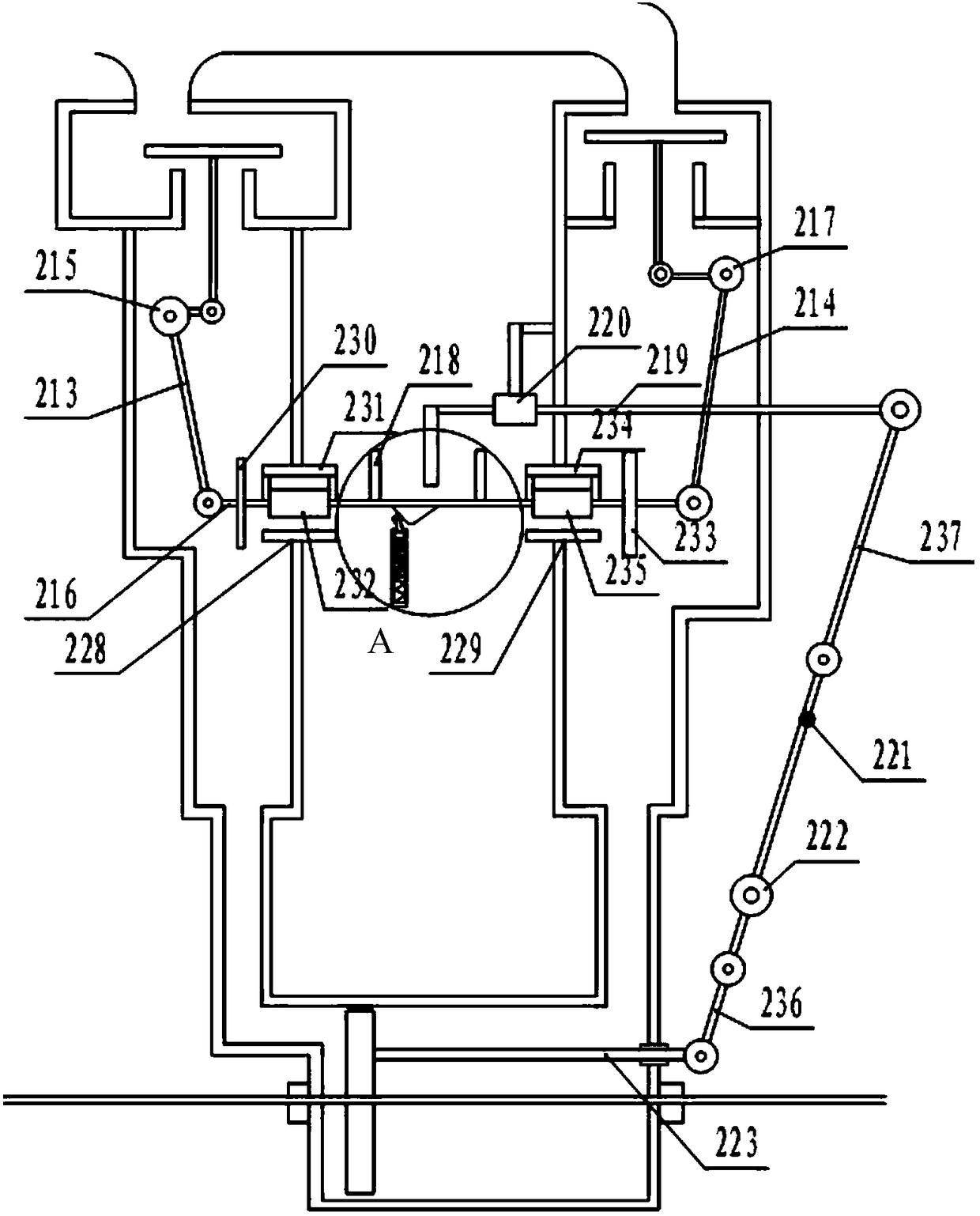
[0023] Embodiment 1: as Figure 1~Figure 7 As shown, a plunger cylinder includes a plunger 201 and a push rod 202, the plunger 201 is placed in the plunger cavity 203, the push rod 202 is fixedly connected to the plunger 201 of the water pump, and one end of the extension is connected to the piston 501 , The plunger cavity 203 is provided with a high-pressure water inlet and outlet 204 .

[0024] Preferably, the above-mentioned high-pressure water inlet and outlet 204 are connected with linked valve five 205 and valve six 206, valve five 205 includes valve plate five 207 and valve cavity five 208, the lower end of valve plate five 207 is connected with valve shaft five 209, valve shaft five 209 It can axially move through valve cavity five 208 and move valve plate five 207 to seal the inner hole in valve cavity five 208. Valve six 206 includes valve plate six 210 and valve cavity six 211. The lower end of valve plate six 210 is connected with Valve shaft six 212, valve shaft ...

Embodiment 2

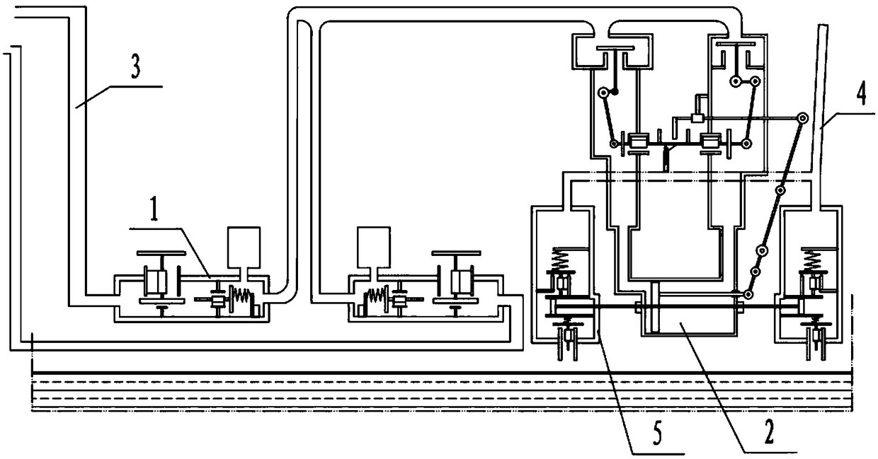
[0029] Embodiment 2: as Figure 1-7 As shown, the above-mentioned plunger cylinder is used for a high-pressure water pump, and the high-pressure water pump includes at least one pressurizing device 1, plunger cylinder 2 and water pump 5, and the water inlet pipe 3 of each pressurizing device 1 is connected to the high-level The water source port and the outlet pipe 4 are connected to the plunger cylinder 2, the push rod 202 of the plunger cylinder 2 is connected to the piston 501 of the water pump 5, the water inlet of the water pump 5 is connected to the low water source port, and the water outlet is connected to the user water supply pipe.

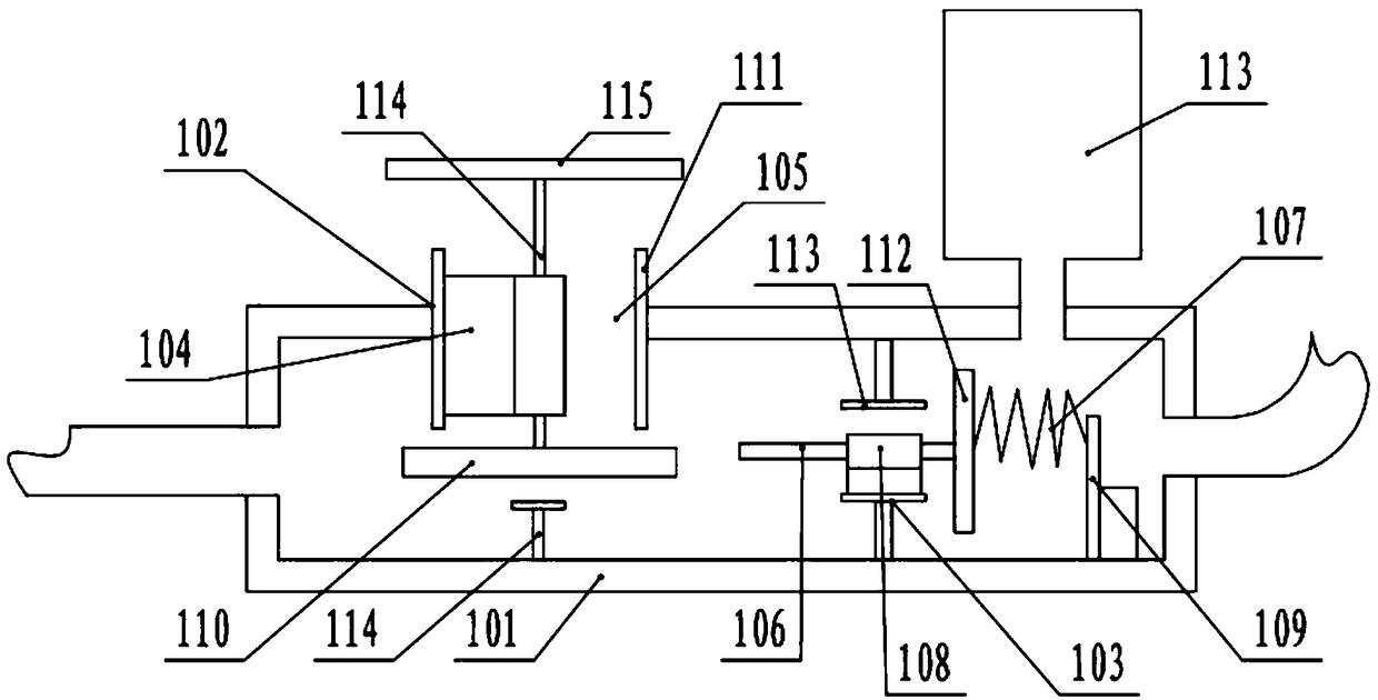
[0030] Preferably, the above-mentioned pressurizing device 1 includes a cavity 101, the side wall of the water inlet end of the cavity 101 is provided with a valve one 102, and the water outlet end is provided with a valve two 103, the valve one 102 includes a valve plate 110 and a valve cavity 111, the valve plate The upper end surface ...


PUM


Abstract

The invention discloses a plunger type cylinder for water pumping. The plunger type cylinder includes a plunger piston and a pushing rod. The plunger piston is installed in a plunger piston chamber. The pushing rod is fixedly connected with the plunger piston. One end stretching out of the pushing rod is connected with a piston of a water pump. The plunger piston chamber is provided with a high pressure water out-in opening. According to the plunger type cylinder, through pushing of the plunger piston in the plunger piston chamber by high pressure water connected by the high pressure water inlet-and-outlet, high pressure power of the water pump is achieved. High level water connected with the high pressure water inlet-and-outlet uses water potential energy as a power source and the use ofelectric energy is avoided so that energy is more saved. Water is used as the power source. The plunger type cylinder for water pumping is free in pollution, low in cost and more environment-friendly.Reciprocating movement of the plunger piston is controlled to realize power pushing of the water suction pump and high pressure water is obtained.

Description

technical field [0001] The invention belongs to the technical field of pressurized water pumps, and relates to a plunger cylinder for pumping water. Background technique [0002] The existing water pump provides the power source through the motor, and the motor drives the water-pressing mechanism inside the pump. The water-pressing mechanism quickly and briefly pushes the water in the pump to move forward to realize the pumping of the pump. For high-lift pumping, this method consumes power Big, expensive, and not environmentally friendly. Contents of the invention [0003] The technical problem to be solved by the present invention is to provide a plunger cylinder for pumping water, capable of pumping water with a high lift, low in cost, and environmentally friendly, so as to overcome the problems existing in the prior art. [0004] The technical solution adopted by the present invention is: a plunger cylinder for pumping water, including a plunger and a push rod, the plu...

Claims


Application Information

Patent Timeline
Patent Type & Authority Patents(China)
IPC IPC(8): F04B9/105F04B23/06F04B53/10
Inventor 郭春郭革委郭会
Owner 东营市虹田石油装备有限公司
Why Eureka
Try Eureka