
An electric three-way valve and refrigeration equipment

A technology of electric three-way valve and refrigeration equipment, which is applied in the direction of mechanical equipment, valve details, valve devices, etc., and can solve problems such as easy bending and falling off

Active Publication Date: 2019-05-31
ZHEJIANG SANHUA INTELLIGENT CONTROLS CO LTD
View PDF1 Cites 0 Cited by
  • Summary
  • Abstract
  • Description
  • Claims
  • Application Information

AI Technical Summary

Problems solved by technology

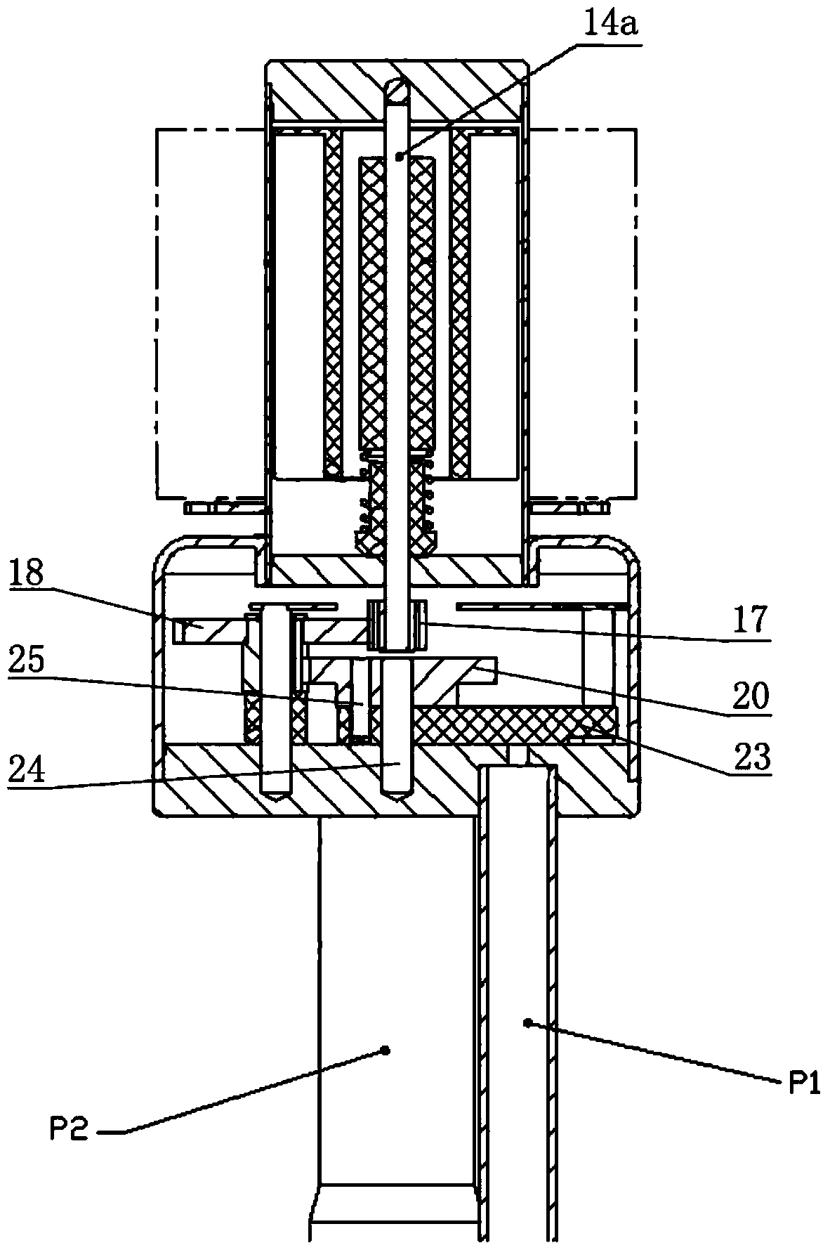
The power of this structure is amplified dozens of times by the reduction gear 18, and then transmitted to the executive gear 20, the executive gear 20 will give a large radial force to the central shaft 24, and the single-ended fixation of the central shaft 24 is prone to bending and falling off

Method used


Image

  • An electric three-way valve and refrigeration equipment
  • An electric three-way valve and refrigeration equipment
  • An electric three-way valve and refrigeration equipment

Examples


Embodiment Construction

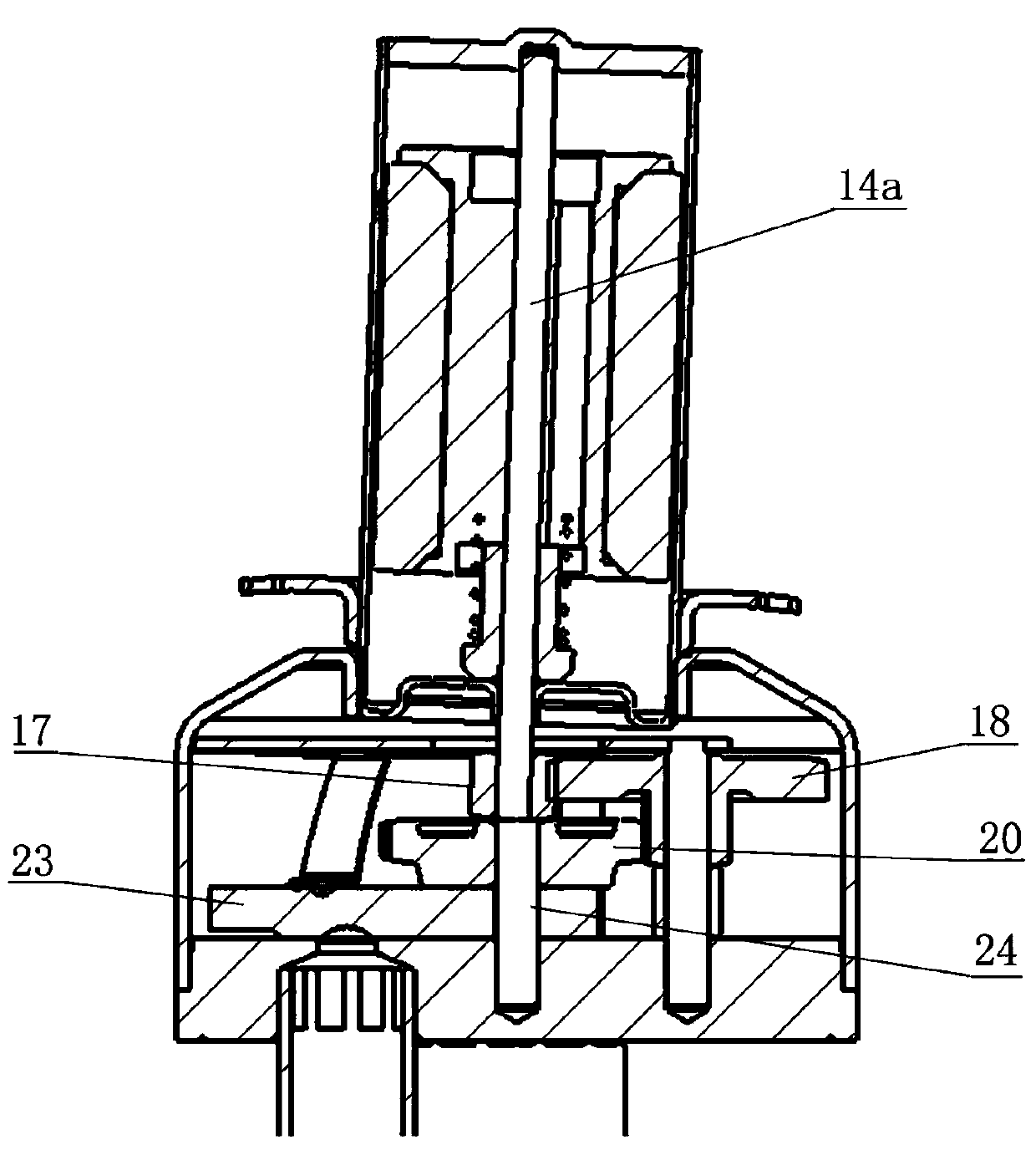
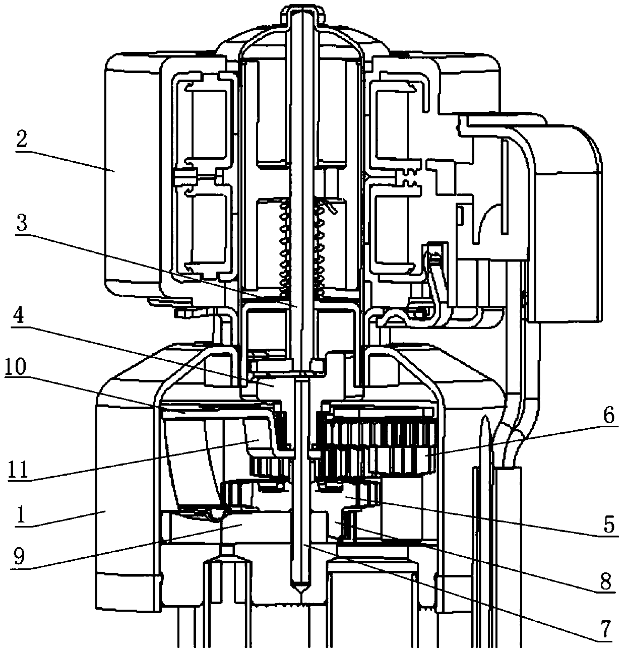
[0033] The core of the present invention is to ensure the coaxiality between the gears by installing the power gear and the executive gear on the same central shaft, so as to eliminate the phenomenon that the gear shafts cannot be meshed or stuck due to poor coaxiality of the gear shafts. At the same time, a bending part with a shaft hole is added on the liner to fix the upper end of the central shaft to ensure the stability of the central shaft.

[0034] In order to enable those skilled in the art to better understand the solution of the present invention, the present invention will be further described in detail below in conjunction with the accompanying drawings and specific embodiments.

[0035] Please refer to image 3 , Figure 4 , image 3 It is a cut-away schematic diagram of a specific embodiment of the electric three-way valve provided by the present invention; Figure 4 It is a cross-sectional view of the power gear and the execution gear installed on the central...


PUM


Abstract

The invention discloses an electric tee valve. The electric tee valve comprises a valve body (1) and a coil (2). A power gear (4), an execution gear (5) and a lining plate (10) are arranged in the valve body (1). The power gear (4) is engaged with the execution gear (5) through a speed reduction gear (6) for transmission, and the power gear (4) and the execution gear (5) are installed on a centershaft (7) together and distributed up and down in a spaced mode. The lining plate (10) is provided with a bent portion (11), and the center shaft (7) is sleeved with the bent portion (11) through a shaft hole (12). The power gear and the execution gear of the tee valve are arranged on the same center shaft, so that the coaxiality of the gears is greatly enhanced, and the phenomenon that gear shafts cannot be normally engaged or clamped to each other due to poor coaxiality is effectively avoided; and in addition, the center shaft is fixed with the lining plate and the both ends of a valve seat,so that the center shaft is more firm and is prevented from bending and disengaging.

Description

technical field [0001] The invention relates to the technical field of valves, in particular to an electric three-way valve used in refrigeration equipment for controlling on-off and flow direction of refrigerant. The present invention also relates to refrigeration equipment provided with the electric three-way valve. Background technique [0002] At present, the three-way valves used in refrigeration equipment, especially the electric three-way valves in the heat pump air-conditioning pipeline, mostly control the on-off and flow direction of the refrigerant through the slider switching in the valve. [0003] The electric three-way valve is mainly composed of a valve body and a coil. The valve body has three valve ports. The direction of the magnetic rotor can be clockwise or counterclockwise, so that the magnetic rotor part rotates in the direction of the force. A series of gear transmissions in the valve body transmit the force to the slider. Switching between the two va...

Claims


Application Information

Patent Timeline
Patent Type & Authority Patents(China)
IPC IPC(8): F16K31/06F16K31/53
Inventor 不公告发明人
Owner ZHEJIANG SANHUA INTELLIGENT CONTROLS CO LTD
Learn More