
WIFI antenna

An antenna and wireless receiving technology, applied in the field of WIFI antenna, can solve the problem of low gain of WIFI antenna

Inactive Publication Date: 2018-01-23
SHENZHEN GONGJIN ELECTRONICS CO LTD
View PDF6 Cites 2 Cited by
  • Summary
  • Abstract
  • Description
  • Claims
  • Application Information

AI Technical Summary

Problems solved by technology

[0004] Based on this, it is necessary to provide a WIFI antenna for how to improve the problem of how to improve the low gain of the traditional WIFI antenna in order to match the appearance of the smart terminal.

Method used


Image

  • WIFI antenna
  • WIFI antenna
  • WIFI antenna

Examples


Embodiment Construction

[0025] In order to facilitate the understanding of the present invention, the present invention will be described more fully below with reference to the associated drawings. Preferred embodiments of the invention are shown in the accompanying drawings. However, the present invention can be embodied in many different forms and is not limited to the embodiments described herein. On the contrary, these embodiments are provided to make the understanding of the disclosure of the present invention more thorough and comprehensive.

[0026] Unless otherwise defined, all technical and scientific terms used herein have the same meaning as commonly understood by one of ordinary skill in the technical field of the invention. The terminology used herein in the description of the invention is for the purpose of describing specific embodiments only, and is not intended to limit the present invention. As used herein, the term "and / or" includes any and all combinations of one or more of the ...


PUM


Abstract

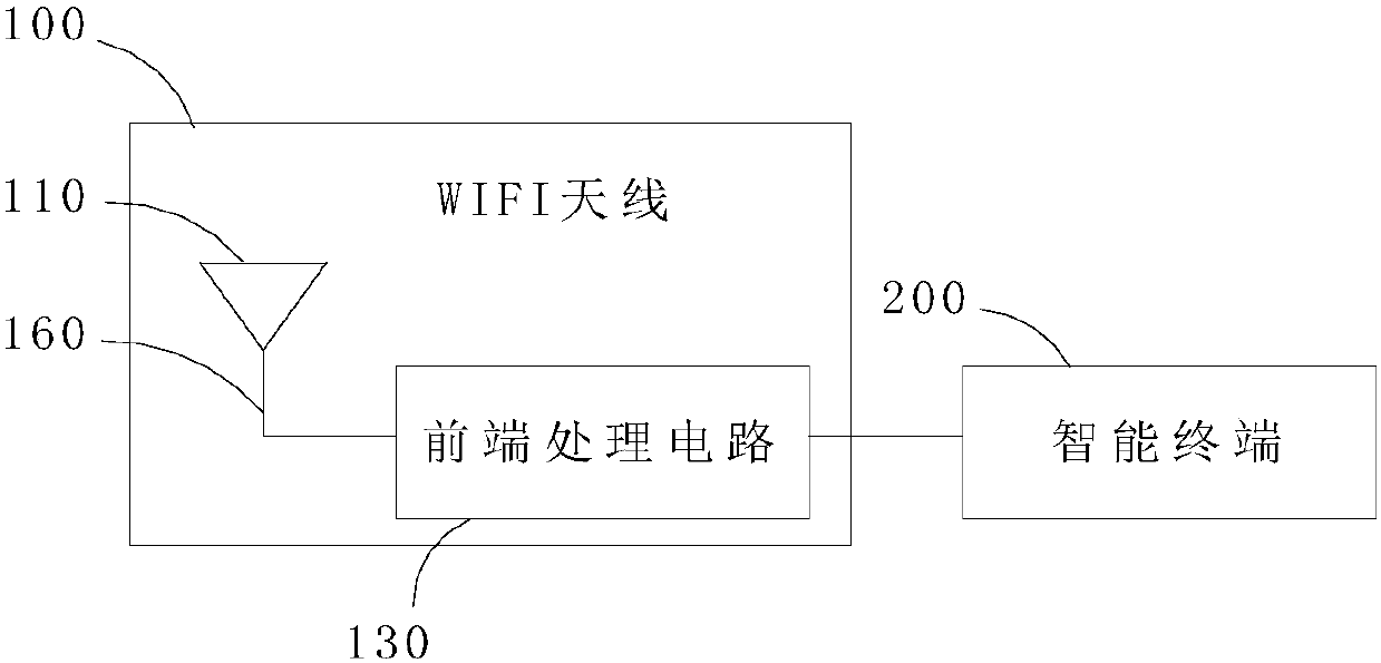
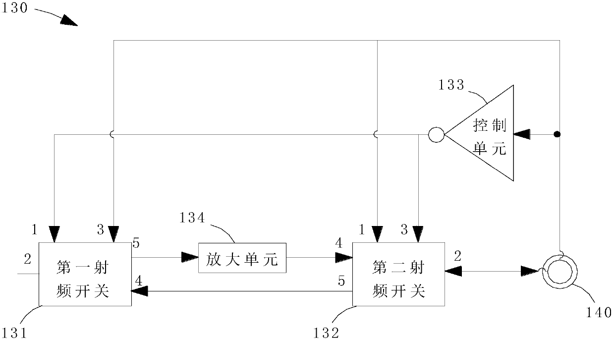
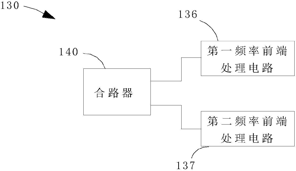
The present invention relates to a WIFI antenna. The antenna comprises a radiating end used for wirelessly transmitting or wirelessly receiving signals; the WIFI antenna further comprises a front-endprocessing circuit; the front-end processing circuit is connected with the radiating end through a radio frequency cable; and the front-end processing circuit is further used for connecting an intelligent terminal; the front-end processing circuit is used for switching a receiving mode and a transmitting mode; in the receiving mode, the front-end processing circuit is used for amplifying signals wirelessly received by the radiating end and sending out the amplified signals; and in the transmitting mode, the front-end processing circuit is used for wirelessly sending out signals transmitted bythe intelligent terminal through the radiating end. The gain of the WIFI antenna, in a very small size, can be increased; and the degree of matching between the WIFI antenna and the shape of the intelligent terminal can be improved, and therefore, the application range of the WIFI antenna can be expanded, and the stability and sensitivity of the signals can be improved.

Description

technical field [0001] The invention relates to the technical field of wireless communication, in particular to a WIFI antenna. Background technique [0002] WIFI (Wireless Fidelity, wireless local area network based on IEEE 802.11b standard) is a technology that allows electronic devices to connect to a wireless local area network (WLAN), and has been more and more widely used. The smart terminal is used to transmit and receive wireless signals through the WIFI antenna, so the performance of the WIFI antenna directly affects the signal transmission performance. [0003] The traditional WIFI antenna usually realizes the effective radiation of the antenna through resonance, and at the same time uses the way of unit array to increase the gain of the antenna. However, although this method can improve the strength of the wireless signal, the size of the antenna is relatively large, which does not match the appearance of the smart terminal. Therefore, in order to ensure a match...

Claims


Application Information

Patent Timeline
IPC IPC(8): H01Q1/36H01Q1/50H01Q5/10H01Q5/50H01Q23/00
Inventor 戴勤
Owner SHENZHEN GONGJIN ELECTRONICS CO LTD
Learn More