
Fixing fixture

A technology for fixing jigs and positioning columns, which is applied to electrical components, electrical components, etc., can solve problems such as high defect rate, easy assembly deviation, and difficulty in ensuring assembly effect, so as to improve production yield, improve assembly accuracy, and improve The effect of positioning accuracy

Active Publication Date: 2018-01-23
JRD COMM
View PDF10 Cites 2 Cited by
  • Summary
  • Abstract
  • Description
  • Claims
  • Application Information

AI Technical Summary

Problems solved by technology

[0002] At present, there are LED lights on the PCB of smart bracelets on the market. In order to achieve the smallest light shadow seen outside the product and consistent lighting, it is necessary to add assembly parts on the PCB; currently, the assembly parts on the PCB are marked on the PCB. , Assemble the assembly along the marking line, plus manual assembly, this method is easy to be misaligned, the assembly effect is difficult to guarantee, and the defect rate is high; therefore, a tool with fixed positioning is needed to ensure the yield rate of the product

Method used


Image

  • Fixing fixture
  • Fixing fixture
  • Fixing fixture

Examples


Embodiment 1

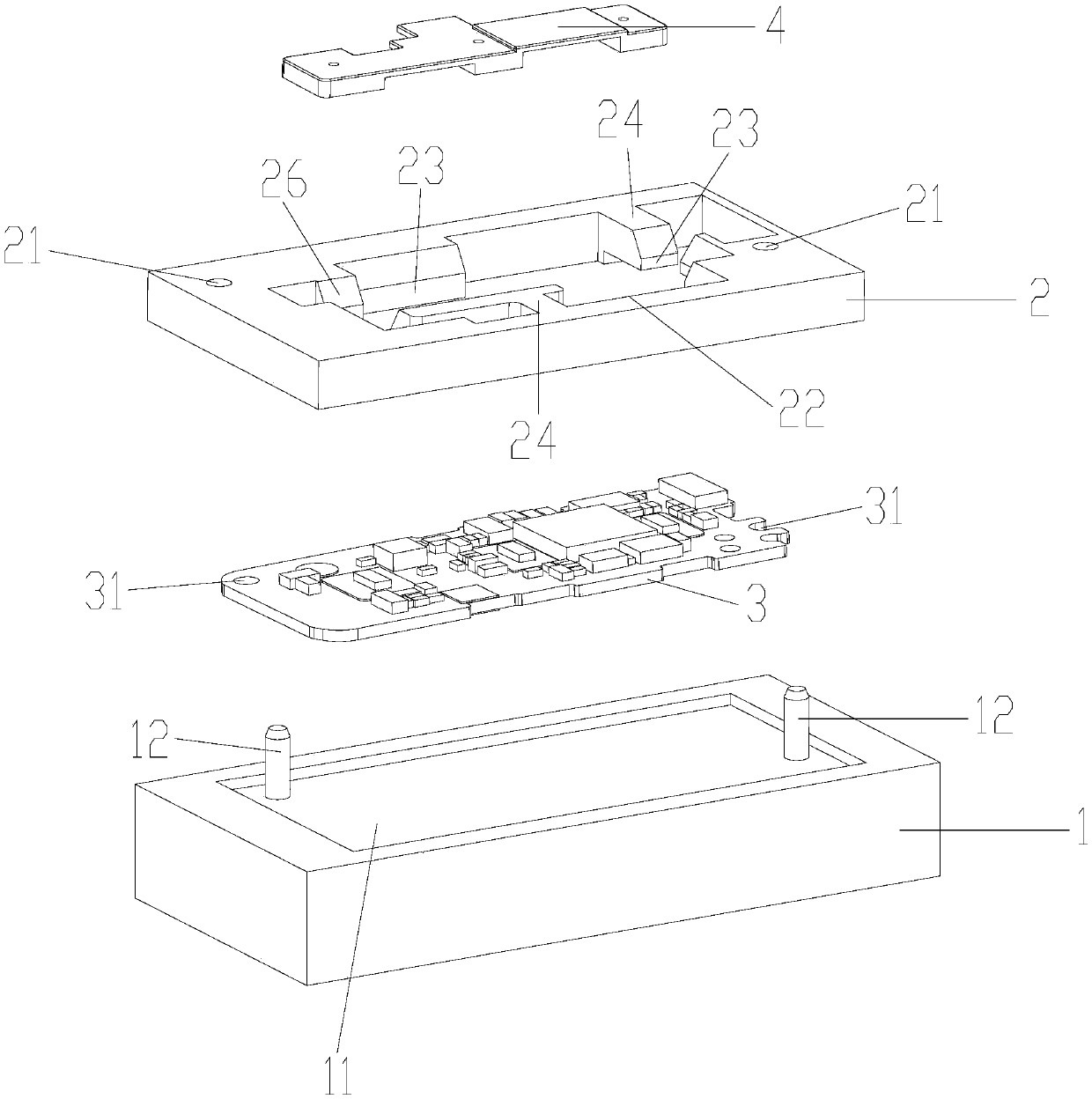
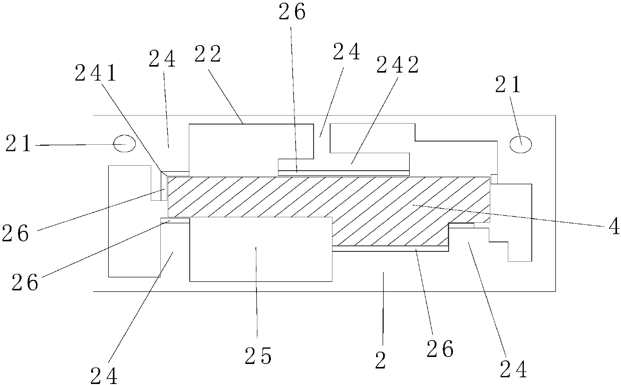
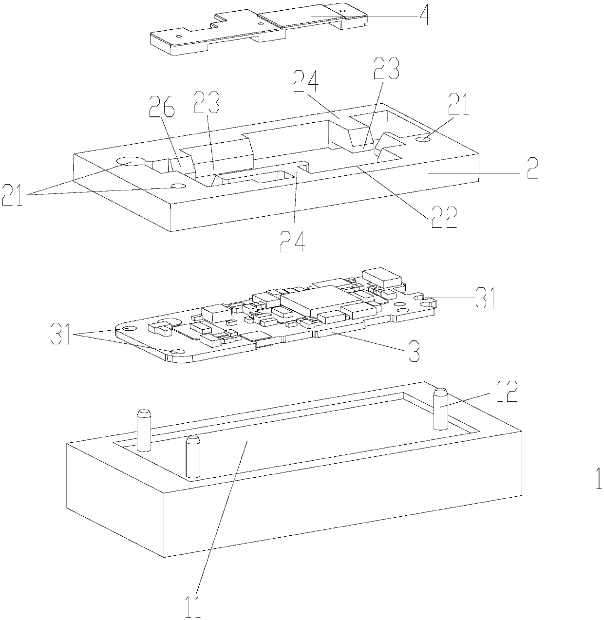
[0021] The following combination figure 1 and figure 2 To illustrate Embodiment 1 of the present invention, in this embodiment, a groove 11 is provided on the surface of the base 1 facing the upper cover 2, the groove 11 is used to carry the PCB board 3, and two positioning holes are arranged in the groove 11. Column 12, the setting position of the positioning column 12 corresponds to the two first positioning holes 31 of the carried PCB board 3, so as to position and fix the PCB board 3; wherein, the shape of the groove 11 is consistent with the outer surface of the PCB board 3 The shapes are interlinked and matched with each other, so that the PCB board 3 can be fixed more stably; the upper cover 2 includes two second positioning holes 21, and the setting positions of the second positioning holes 21 correspond to the positioning columns 12, and at the same time Corresponding to the first positioning hole 31 on the PCB board 3, the upper cover 2 also includes a processing s...


PUM

PropertyMeasurementUnit
Diameteraaaaaaaaaa

Abstract

The invention provides a fixing fixture, which comprises a base for fixing a PCB and an upper cover for limiting movement of an assembly unit, wherein the base is provided with at least two positioning columns; the PCB is provided with first positioning holes with positions corresponding to the positioning columns; the upper cover comprises second positioning holes corresponding to the positioningcolumns and a processing through groove for limiting movement of the assembly unit; and the opposite side walls between the processing through groove and the assembly unit are provided with positioning surfaces contacted with the assembly unit. In comparison with the prior art, through the match between the positioning columns on the fixture base and the positioning holes on the upper cover of the fixture, the positioning accuracy is improved; and when the assembly unit is assembled, the assembly area on the PCB is determined through the positioning surface of the upper cover, non offset in the case of assembly of the assembly unit is thus ensured, and the production yield is improved.

Description

technical field [0001] The invention belongs to the field of structural design, and in particular relates to a fixing jig. Background technique [0002] At present, there are LED lights on the PCB of smart bracelets on the market. In order to achieve the smallest light shadow seen outside the product and consistent lighting, it is necessary to add assembly parts on the PCB; currently, the assembly parts on the PCB are marked on the PCB. , Assembling the assembly along the marking line, plus manual assembly, this method is easy to be misaligned, the assembly effect is difficult to guarantee, and the defect rate is high; therefore, a tool with fixed positioning is needed to ensure the product yield. Contents of the invention [0003] In order to solve the above-mentioned problems in the prior art, the present invention provides a positioning jig, so that the positioning of the PCB board when assembling the silicone is more accurate and the deviation is guaranteed. [0004] ...

Claims


Application Information

Patent Timeline
IPC IPC(8): H05K13/04
Inventor 占旺发
Owner JRD COMM
Learn More